


How to Troubleshoot Building Control Systems Quickly with Handheld Test Tools


A building control system is an intelligent management system that can monitor and control a building's temperature, humidity, air quality, lighting, and security through sensors, actuators, controllers, and other devices to improve energy efficiency and operating costs. However, as building control systems become more powerful, troubleshooting becomes more complex. When a system fails, how can it be quickly troubleshot using simple handheld test tools?
In this article, we will introduce some common building control system faults and their solutions, as well as some of the test tools available from Fluke that are suitable for troubleshooting building control systems.
Common Failures and Solutions
Faults in building control systems can be categorised as follows:
- Sensor or actuator failure: This is the most basic failure, which may result in the controller not being able to receive the correct signals or output the correct control commands. For example, a damaged temperature sensor causes the air conditioner to be unable to regulate the temperature; a faulty meter causes inaccurate energy consumption data, etc.
- Controller Alarm: This refers to an abnormality in the controller itself or in the device with which it communicates, resulting in an alarm signal from the controller. For example, a field controller alarm indicates a sensor or actuator failure; a DDC controller alarm indicates that a panel or a building communication is interrupted, and so on.
- Management Workstation Error Reporting: This refers to the inability of management workstations to communicate properly with lower level controllers or devices, causing the workstation to display an error message. For example, the workstation is out of communication with one or more buildings, resulting in an inability to monitor and control the status of that building.
- User Complaints: this is when a person in a building is not satisfied with the environmental conditions and calls to complain. Examples include rooms that are too hot or too cold, poor air quality, insufficient lighting, and so on.
To resolve these faults, it is first necessary to determine the location and cause of the fault. Generally speaking, you can check the following aspects:
- Controller check: log on to the central management controller and check the status and alarm messages of the whole system. If a local fault occurs, there may be a problem with the field controller panel, the analogue circuitry or the sensors or actuators themselves; if a building-wide fault occurs, there may be a problem with the communication between the management controller and the DDC, network routers or switches; if a campus-wide fault occurs, there may be a problem with the Ethernet or IP backbone network.
- Ethernet Check: Verify that the network is working by checking the network connection icon or the Ethernet port link status LED. If there is an anomaly, further testing can be performed using a network diagnostic tool. For example, Fluke's EtherScope network diagnostic tool connects to copper, fibre-optic or wireless Ethernet and provides an overview of a variety of key network performance parameters to help locate network faults.
- Cabling Check: Check that the cabling connecting the faulty device is intact. In the case of standard AWG cabling, a digital multimeter can be used to check for basic cable opens and shorts as well as impedance faults; in the case of twisted-pair (UTP) cabling, a more detailed test can be performed using Fluke's Cable IQ or DTX cable analyser.
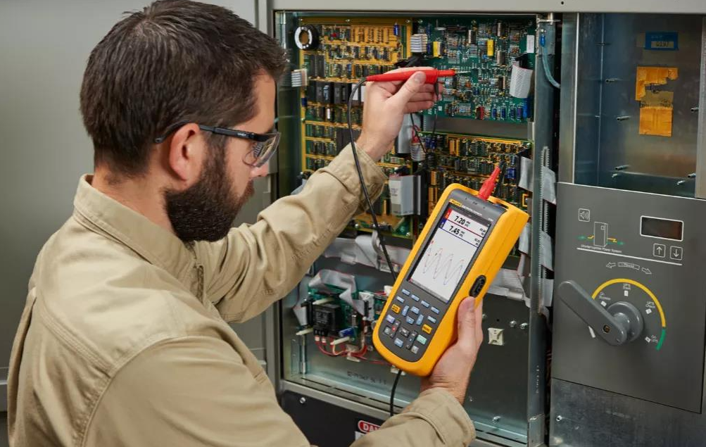
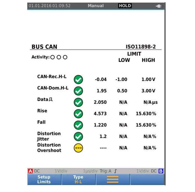
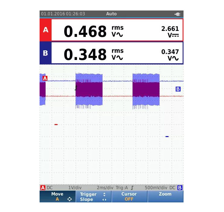
- Signal check: If the cabling checks out fine, then an oscilloscope can be used to capture waveforms and check the quality of the communication signals on the network. For example, Fluke's Fluke 125B Oscilloscope is a portable handheld oscilloscope with an auto mode for capturing waveforms, which allows you to see the waveforms with no fuss when connected. It also features network bus health and physical layer testing to help determine signal throughput, attenuation, distortion and other issues.
- Intermittent faults: Intermittent faults are the most difficult to diagnose because they occur randomly and are difficult to capture. In this case an oscilloscope with a record or trend capture mode can be used to save time and improve efficiency by automatically capturing the fault event waveform. Such faults are sometimes caused by degradation of equipment, control or cabling performance due to vibration or environmental changes. Another possible cause is installation errors. Such errors include network cabling near high voltage sources or inductive loads, using the incorrect type of cable, or cables that are too long.
- Power Failure: Power problems can also cause intermittent tripping or failure of equipment. There are the following possible causes of power failures: a system upgrade has recently occurred and the old power supply may be overloaded or unbalanced; the power supplied by the original distribution system does not meet the new control system's requirements for a clean power supply; new equipment may be backfeeding harmonic disturbances back into the power supply; and, in some cases, refurbishments may have triggered the failure, making the cause of the failure less obvious. If a power supply failure is suspected, use Fluke's Fluke 1736 power quality recorder, which not only continuously records voltage, current, frequency, and harmonics, but also captures events such as power outages and trips. With today's widespread use of computers and other office equipment, it helps engineers understand the true cause of a fault.
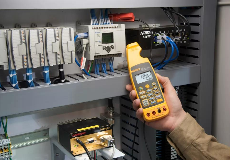
- Analogue checking: For multi-layer type control systems, frequent diagnosis of analogue signal faults is also required. Again, the first step is to locate the fault. If a fault occurs only in one part of the building, it is likely to be a fault in the analogue component, as this is the most fundamental part of the building control system architecture. Sensors communicate by converting their output signals to 4-20 mA DC currents, while other systems use DC 1V-5V or DC 0V/2V-10V circuits. At this point, the fastest way to troubleshoot is to use a milliamp clamp meter to measure the current or voltage between the sensor or actuator and the field controller, as well as to simulate the control signal returned to the controller. Fluke's Fluke 773 milliamp process clamp meter measures both milliamp signals and outputs 4-20 mA and 1V-5V or 0V/2V-10V signals. It helps engineers to quickly measure analogue signals and troubleshoot control systems without removing wires.
A building control system is an intelligent management system that can monitor and control a building's temperature, humidity, air quality, lighting, and security through sensors, actuators, controllers, and other devices to improve energy efficiency and operating costs. However, as building control systems become more powerful, troubleshooting becomes more complex. When a system fails, how can it be quickly troubleshot using simple handheld test tools?
In this article, we will introduce some common building control system faults and their solutions, as well as some of the test tools available from Fluke that are suitable for troubleshooting building control systems.
Common Failures and Solutions
Faults in building control systems can be categorised as follows:
- Sensor or actuator failure: This is the most basic failure, which may result in the controller not being able to receive the correct signals or output the correct control commands. For example, a damaged temperature sensor causes the air conditioner to be unable to regulate the temperature; a faulty meter causes inaccurate energy consumption data, etc.
- Controller Alarm: This refers to an abnormality in the controller itself or in the device with which it communicates, resulting in an alarm signal from the controller. For example, a field controller alarm indicates a sensor or actuator failure; a DDC controller alarm indicates that a panel or a building communication is interrupted, and so on.
- Management Workstation Error Reporting: This refers to the inability of management workstations to communicate properly with lower level controllers or devices, causing the workstation to display an error message. For example, the workstation is out of communication with one or more buildings, resulting in an inability to monitor and control the status of that building.
- User Complaints: this is when a person in a building is not satisfied with the environmental conditions and calls to complain. Examples include rooms that are too hot or too cold, poor air quality, insufficient lighting, and so on.
To resolve these faults, it is first necessary to determine the location and cause of the fault. Generally speaking, you can check the following aspects:
- Controller check: log on to the central management controller and check the status and alarm messages of the whole system. If a local fault occurs, there may be a problem with the field controller panel, the analogue circuitry or the sensors or actuators themselves; if a building-wide fault occurs, there may be a problem with the communication between the management controller and the DDC, network routers or switches; if a campus-wide fault occurs, there may be a problem with the Ethernet or IP backbone network.
- Ethernet Check: Verify that the network is working by checking the network connection icon or the Ethernet port link status LED. If there is an anomaly, further testing can be performed using a network diagnostic tool. For example, Fluke's EtherScope network diagnostic tool connects to copper, fibre-optic or wireless Ethernet and provides an overview of a variety of key network performance parameters to help locate network faults.
- Cabling Check: Check that the cabling connecting the faulty device is intact. In the case of standard AWG cabling, a digital multimeter can be used to check for basic cable opens and shorts as well as impedance faults; in the case of twisted-pair (UTP) cabling, a more detailed test can be performed using Fluke's Cable IQ or DTX cable analyser.
- Signal check: If the cabling checks out fine, then an oscilloscope can be used to capture waveforms and check the quality of the communication signals on the network. For example, Fluke's Fluke 125B Oscilloscope is a portable handheld oscilloscope with an auto mode for capturing waveforms, which allows you to see the waveforms with no fuss when connected. It also features network bus health and physical layer testing to help determine signal throughput, attenuation, distortion and other issues.
- Intermittent faults: Intermittent faults are the most difficult to diagnose because they occur randomly and are difficult to capture. In this case an oscilloscope with a record or trend capture mode can be used to save time and improve efficiency by automatically capturing the fault event waveform. Such faults are sometimes caused by degradation of equipment, control or cabling performance due to vibration or environmental changes. Another possible cause is installation errors. Such errors include network cabling near high voltage sources or inductive loads, using the incorrect type of cable, or cables that are too long.
- Power Failure: Power problems can also cause intermittent tripping or failure of equipment. There are the following possible causes of power failures: a system upgrade has recently occurred and the old power supply may be overloaded or unbalanced; the power supplied by the original distribution system does not meet the new control system's requirements for a clean power supply; new equipment may be backfeeding harmonic disturbances back into the power supply; and, in some cases, refurbishments may have triggered the failure, making the cause of the failure less obvious. If a power supply failure is suspected, use Fluke's Fluke 1736 power quality recorder, which not only continuously records voltage, current, frequency, and harmonics, but also captures events such as power outages and trips. With today's widespread use of computers and other office equipment, it helps engineers understand the true cause of a fault.
- Analogue checking: For multi-layer type control systems, frequent diagnosis of analogue signal faults is also required. Again, the first step is to locate the fault. If a fault occurs only in one part of the building, it is likely to be a fault in the analogue component, as this is the most fundamental part of the building control system architecture. Sensors communicate by converting their output signals to 4-20 mA DC currents, while other systems use DC 1V-5V or DC 0V/2V-10V circuits. At this point, the fastest way to troubleshoot is to use a milliamp clamp meter to measure the current or voltage between the sensor or actuator and the field controller, as well as to simulate the control signal returned to the controller. Fluke's Fluke 773 milliamp process clamp meter measures both milliamp signals and outputs 4-20 mA and 1V-5V or 0V/2V-10V signals. It helps engineers to quickly measure analogue signals and troubleshoot control systems without removing wires.