Optical Communication How to test TX\RX and what equipment is needed?
How to test TX,RX and what equipment is needed?
TX and RX are two important concepts in a communication system, representing Transmitter and Receiver respectively. In a communication system, the Transmitter is responsible for converting information signals into electromagnetic waves and sending them out, and the Receiver is responsible for receiving the electromagnetic waves and reducing them to information signals. Therefore, testing the performance of TX and RX is an important step to ensure that the communication system works properly.
How to test TX and RX? Testing TX and RX requires the following indicators:
- Output power: Output power is the power of the electromagnetic wave output from the transmitter, which is the amount of energy. The higher the output power, the stronger the transmitter is and the longer distance it can cover. Output power can be measured with a Power Meter.
- Frequency: Frequency is the number of periodic changes in an electromagnetic wave, also known as the rate of oscillation. The higher the frequency, the shorter the electromagnetic wave and the more information it can carry. Frequency can be measured with a Spectrum Analyzer.
- Modulation: Modulation refers to the method by which a transmitter converts an information signal into an electromagnetic wave, also known as coding. Different modulation methods have different advantages and disadvantages, such as anti-interference ability, transmission rate, bandwidth occupation, etc.. The modulation method can be measured with a Vector Signal Analyzer.
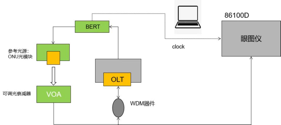
- BER: BER is the probability that the receiver will make an error when restoring the information signal, i.e. the degree of distortion. The lower the BER, the more accurate the receiver is in ensuring the integrity of the message. The BER can be measured with a Bit Error Rate Tester.
These are some of the basic indicators and equipment needed to test TX and RX. Of course, according to different communication systems and application scenarios, other indicators and equipment may also be required. For example, in wireless communication, channel characteristics, multipath effect, interference and other factors need to be considered. Therefore, when testing TX and RX, it is necessary to choose the appropriate methods and tools according to the specific situation.
In the following, we will use a specific example to illustrate how to test TX and RX. Suppose we want to test a wireless communication system based on QPSK (Quad-Phase Shift Keying) modulation, operating in the 2.4GHz frequency band, with an output power of 10dBm and a target BER of 10^-6^.
Firstly, we need to prepare the following equipment:
- A QPSK transmitter
- A QPSK receiver
- A power meter
- A spectrum analyser.
- A vector signal analyser.
- A BER meter.
- Some cables and antennas

The following steps are for testing:
1. Connect the transmitter to the power meter and set the parameters of the transmitter (e.g., frequency, output power, modulation method, etc.). Switch on the transmitter and observe whether the output power displayed on the power meter is as expected.
2. Connect the transmitter to the spectrometer and set the parameters of the spectrometer (e.g. centre frequency, scanning range, resolution bandwidth, etc.). Switch on the spectrometer and observe whether the spectrum displayed on the spectrometer is as expected.
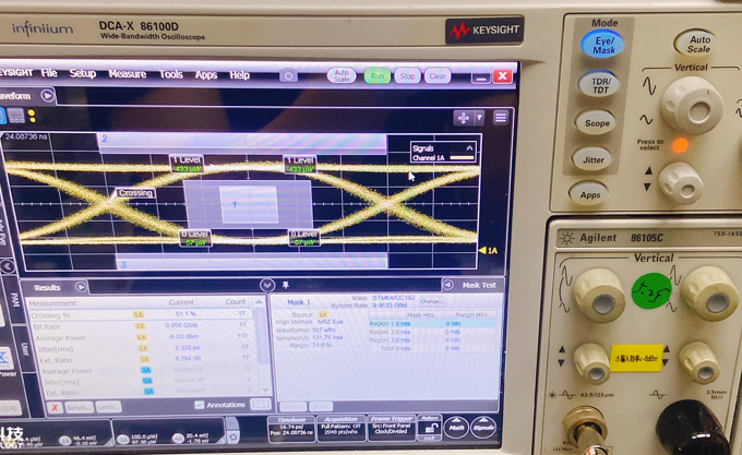
3. Connect the transmitter to the vector signal analyser and set the parameters of the vector signal analyser (e.g. centre frequency, sampling rate, modulation mode, etc.). Turn on the vector signal analyser and observe whether the modulation quality indicators (e.g. error vector amplitude, phase error, constellation diagram, etc.) displayed on the vector signal analyser are as expected.
4. Connect the transmitter and receiver through the antenna and set the parameters of the receiver (e.g. frequency, gain, modulation mode, etc.). Switch on the receiver and observe whether the signal strength displayed on the receiver is as expected.
5. Connect the receiver to the BER and set the parameters of the BER (e.g. bit rate, synchronisation method, BER threshold, etc.). Switch on the BER and observe whether the BER displayed on the BER is as expected.

With the above steps, we can perform a complete test on TX and RX to get the relevant performance indicators. If the test results do not meet the requirements, we can adjust or optimise TX and RX until the target is reached.
How to test TX,RX and what equipment is needed?
TX and RX are two important concepts in a communication system, representing Transmitter and Receiver respectively. In a communication system, the Transmitter is responsible for converting information signals into electromagnetic waves and sending them out, and the Receiver is responsible for receiving the electromagnetic waves and reducing them to information signals. Therefore, testing the performance of TX and RX is an important step to ensure that the communication system works properly.
How to test TX and RX? Testing TX and RX requires the following indicators:
- Output power: Output power is the power of the electromagnetic wave output from the transmitter, which is the amount of energy. The higher the output power, the stronger the transmitter is and the longer distance it can cover. Output power can be measured with a Power Meter.
- Frequency: Frequency is the number of periodic changes in an electromagnetic wave, also known as the rate of oscillation. The higher the frequency, the shorter the electromagnetic wave and the more information it can carry. Frequency can be measured with a Spectrum Analyzer.
- Modulation: Modulation refers to the method by which a transmitter converts an information signal into an electromagnetic wave, also known as coding. Different modulation methods have different advantages and disadvantages, such as anti-interference ability, transmission rate, bandwidth occupation, etc.. The modulation method can be measured with a Vector Signal Analyzer.
- BER: BER is the probability that the receiver will make an error when restoring the information signal, i.e. the degree of distortion. The lower the BER, the more accurate the receiver is in ensuring the integrity of the message. The BER can be measured with a Bit Error Rate Tester.
These are some of the basic indicators and equipment needed to test TX and RX. Of course, according to different communication systems and application scenarios, other indicators and equipment may also be required. For example, in wireless communication, channel characteristics, multipath effect, interference and other factors need to be considered. Therefore, when testing TX and RX, it is necessary to choose the appropriate methods and tools according to the specific situation.
In the following, we will use a specific example to illustrate how to test TX and RX. Suppose we want to test a wireless communication system based on QPSK (Quad-Phase Shift Keying) modulation, operating in the 2.4GHz frequency band, with an output power of 10dBm and a target BER of 10^-6^.
Firstly, we need to prepare the following equipment:
- A QPSK transmitter
- A QPSK receiver
- A power meter
- A spectrum analyser.
- A vector signal analyser.
- A BER meter.
- Some cables and antennas

The following steps are for testing:
1. Connect the transmitter to the power meter and set the parameters of the transmitter (e.g., frequency, output power, modulation method, etc.). Switch on the transmitter and observe whether the output power displayed on the power meter is as expected.
2. Connect the transmitter to the spectrometer and set the parameters of the spectrometer (e.g. centre frequency, scanning range, resolution bandwidth, etc.). Switch on the spectrometer and observe whether the spectrum displayed on the spectrometer is as expected.
3. Connect the transmitter to the vector signal analyser and set the parameters of the vector signal analyser (e.g. centre frequency, sampling rate, modulation mode, etc.). Turn on the vector signal analyser and observe whether the modulation quality indicators (e.g. error vector amplitude, phase error, constellation diagram, etc.) displayed on the vector signal analyser are as expected.
4. Connect the transmitter and receiver through the antenna and set the parameters of the receiver (e.g. frequency, gain, modulation mode, etc.). Switch on the receiver and observe whether the signal strength displayed on the receiver is as expected.
5. Connect the receiver to the BER and set the parameters of the BER (e.g. bit rate, synchronisation method, BER threshold, etc.). Switch on the BER and observe whether the BER displayed on the BER is as expected.

With the above steps, we can perform a complete test on TX and RX to get the relevant performance indicators. If the test results do not meet the requirements, we can adjust or optimise TX and RX until the target is reached.


