


PCIe TX/RX Physical Layer Signal Integrity Test Methods Explained


PCIe has both a serial communications interface and a storage interface, unlike SAS and SATA, thus enabling additional industry scalability. PCIe supports full-duplex communication based on a point-to-point bus topology between the followers (system/host) and the endpoints (plug-ins). The specifications are developed and maintained by the PCI-SIG, an association of more than 900 companies.
The PCIe physical layer includes:
● Differential low voltage 100 MHz reference clock
● Expandable path widths: x1, x2, x4, x8, x12, x16, x32
Expandable speeds: 2.5GT/s (Gen1), 5GT/s (Gen2), 8GT/s (Gen3), 16GT/s (Gen4)
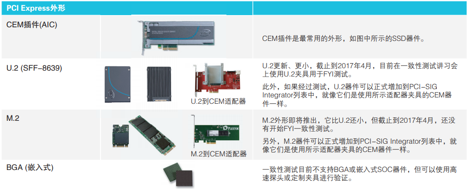
● Different connectors are used in conformance testing, such as CEM, U.2 (SFF-8639), M.2, or soldered directly to the PCB.
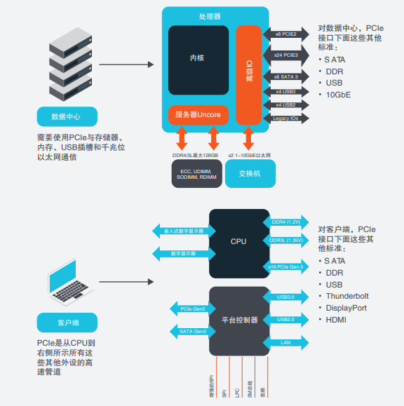
PCI Express- Where is it used?
PCIe is a major emerging high performance storage and serial bus used in data centre and client applications.PCIe enables data communication between peripherals. Both data centre and client applications have a core processor that provides raw processing power to the architecture on the host system. Both applications must also interface with a variety of peripheral devices such as SATA drives, USB devices, and so on. Between the composite host and the endpoint devices, there are typically many circuit-length lossy channels and connectors that introduce noise, crosstalk, timing irregularities, and other impairments. Therefore, PCIe devices on the client and data centre side must be able to reliably demonstrate PCI compliance, compensate for impairments, and interoperate with PCIe devices.
PCIe Gen4 Update
As the industry needs to increase data throughput and bandwidth throughput, PCIe data rates must increase to keep pace with demand. That's why one of the biggest changes in Gen4 is a 2x increase in data rates, from 8GT/s in Gen3 to 16GT/s in Gen4.
Below is a list of the major enhancements that the latest Gen4 standard brings to the market.
RJ (Randomness Jitter) has been reduced from 3 ps (PCIe3) to ~1 ps (PCIe4) for the pressurised Rx eye diagram parameter.
● Gen4 connectors are backward compatible with Gen1/2/3.
● Limited lanes: Repeaters (redrivers and retimers) are required for longer lanes and/or a second connector.
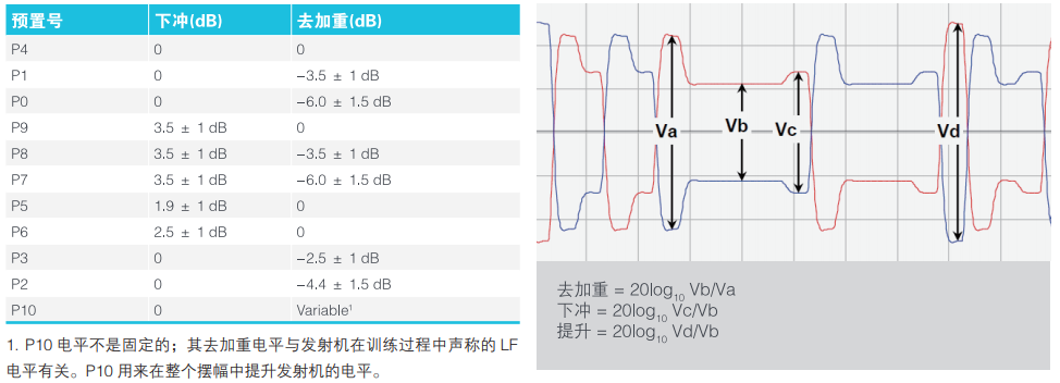
● When testing both Gen3 and Gen4 on the same device, the number of individual presets tested is doubled to a total of 22. 11 presets (P0 ~ P10) for Gen3 and 11 presets (P0 ~ P10) for Gen4.
The new Rx pass margin function measures the last eye height (EH)/eye width (EW) margin of the channel.
The Gen4 CEM specification was released rev 0.5.
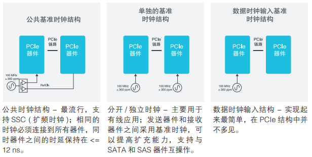
Traditionally, PCIe has used a common clock architecture, which is more challenging to test than the composite and chips that can deviate from the same clock configuration rather than run at different intervals. Public clocking is a more accurate architecture, but less flexible to integrate into a system. With the adoption of the Gen4 standard, systems are expected to have more separate/independent clock architectures. Clock stability is essential to support three different clock input architectures

PCI Express Form Factor
In order to facilitate reliable data transfer between transmitter and receiver devices, PCI-SIG imposes very stringent requirements on the reference clock. The standard specifies the use of a 100 MHz clock (Refclk), frequency stability of more than ±300 ppm on both transmitter and receiver devices, and support for three different clock architectures, coordinated with the root composite chip and the endpoint chip.
Conformance Test Presets
To pass conformance testing for interoperability, each device requires PCI-SIG certification, which is based on a list of presets, or transmitter equalisation settings, ranging from a low data rate of 2.5 Gb/s up to the latest high data rate of 16 Gb/s. These presets are used to equalise channel losses and optimise signal integrity on the link. These presets are used to equalise channel losses and optimise signal integrity on the link. Each preset is a specific combination of downslope and de-emphasis applied from the host to the endpoint.
The following table details the 11 presets for Gen3 and Gen4; the DUT must support all presets. To reduce test time and increase the speed of automation, it is recommended that you use 100MHz clock bursts as inputs to the conformance test fixture to quickly switch between these presets. If you can automate the preset tests using 100MHz clock burst dip switches, you can save valuable test time by automatically capturing and analysing individual metrics such as jitter, voltage and timing.
Many early implementers of PCI-SIG testing prefer to use tools like Tektronix DPOJET and SDLA software for early Gen4 characterisation and debugging.
Basic Specification Transmitter (Tx) Testing
CEM and U.2 Specification Transmitter (Tx) Testing
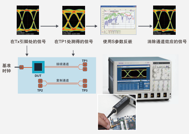
The measurements on the transmitter pins are specified directly in the basic transmitter test of the chip device. Since access to the pins is sometimes not possible, measurements should be performed as close as possible to this reference point.
Systems and Plug-ins In CEM level transmitter testing, the signal integrity of the transmitter is measured as seen in the receiver slitter, but due to the form factor and the fixtures used in the testing process, direct access to the signal is not possible. To ensure measurement accuracy, two important components should be implemented as described below.
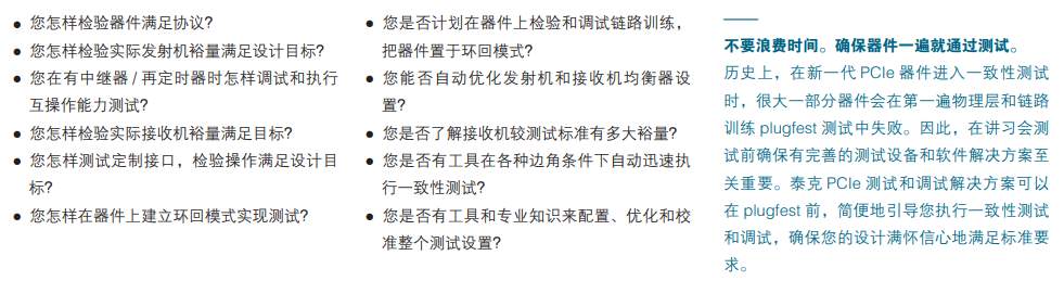
Key Considerations in PCIe Test and Debug Setups
As the speed and complexity of PCIe continues to increase with the advent of the Gen 4 standard, engineers are faced with new design challenges, shorter product development cycles, and the need to understand new standards specifications and new conformance test requirements.
Here are some key questions to ask before you tackle testing and debugging Gen3 or Gen4 PCIe devices:
PCIe has both a serial communications interface and a storage interface, unlike SAS and SATA, thus enabling additional industry scalability. PCIe supports full-duplex communication based on a point-to-point bus topology between the followers (system/host) and the endpoints (plug-ins). The specifications are developed and maintained by the PCI-SIG, an association of more than 900 companies.
The PCIe physical layer includes:
● Differential low voltage 100 MHz reference clock
● Expandable path widths: x1, x2, x4, x8, x12, x16, x32
Expandable speeds: 2.5GT/s (Gen1), 5GT/s (Gen2), 8GT/s (Gen3), 16GT/s (Gen4)
● Different connectors are used in conformance testing, such as CEM, U.2 (SFF-8639), M.2, or soldered directly to the PCB.
PCI Express- Where is it used?
PCIe is a major emerging high performance storage and serial bus used in data centre and client applications.PCIe enables data communication between peripherals. Both data centre and client applications have a core processor that provides raw processing power to the architecture on the host system. Both applications must also interface with a variety of peripheral devices such as SATA drives, USB devices, and so on. Between the composite host and the endpoint devices, there are typically many circuit-length lossy channels and connectors that introduce noise, crosstalk, timing irregularities, and other impairments. Therefore, PCIe devices on the client and data centre side must be able to reliably demonstrate PCI compliance, compensate for impairments, and interoperate with PCIe devices.
PCIe Gen4 Update
As the industry needs to increase data throughput and bandwidth throughput, PCIe data rates must increase to keep pace with demand. That's why one of the biggest changes in Gen4 is a 2x increase in data rates, from 8GT/s in Gen3 to 16GT/s in Gen4.
Below is a list of the major enhancements that the latest Gen4 standard brings to the market.
RJ (Randomness Jitter) has been reduced from 3 ps (PCIe3) to ~1 ps (PCIe4) for the pressurised Rx eye diagram parameter.
● Gen4 connectors are backward compatible with Gen1/2/3.
● Limited lanes: Repeaters (redrivers and retimers) are required for longer lanes and/or a second connector.
● When testing both Gen3 and Gen4 on the same device, the number of individual presets tested is doubled to a total of 22. 11 presets (P0 ~ P10) for Gen3 and 11 presets (P0 ~ P10) for Gen4.
The new Rx pass margin function measures the last eye height (EH)/eye width (EW) margin of the channel.
The Gen4 CEM specification was released rev 0.5.
Traditionally, PCIe has used a common clock architecture, which is more challenging to test than the composite and chips that can deviate from the same clock configuration rather than run at different intervals. Public clocking is a more accurate architecture, but less flexible to integrate into a system. With the adoption of the Gen4 standard, systems are expected to have more separate/independent clock architectures. Clock stability is essential to support three different clock input architectures
PCI Express Form Factor
In order to facilitate reliable data transfer between transmitter and receiver devices, PCI-SIG imposes very stringent requirements on the reference clock. The standard specifies the use of a 100 MHz clock (Refclk), frequency stability of more than ±300 ppm on both transmitter and receiver devices, and support for three different clock architectures, coordinated with the root composite chip and the endpoint chip.
Conformance Test Presets
To pass conformance testing for interoperability, each device requires PCI-SIG certification, which is based on a list of presets, or transmitter equalisation settings, ranging from a low data rate of 2.5 Gb/s up to the latest high data rate of 16 Gb/s. These presets are used to equalise channel losses and optimise signal integrity on the link. These presets are used to equalise channel losses and optimise signal integrity on the link. Each preset is a specific combination of downslope and de-emphasis applied from the host to the endpoint.
The following table details the 11 presets for Gen3 and Gen4; the DUT must support all presets. To reduce test time and increase the speed of automation, it is recommended that you use 100MHz clock bursts as inputs to the conformance test fixture to quickly switch between these presets. If you can automate the preset tests using 100MHz clock burst dip switches, you can save valuable test time by automatically capturing and analysing individual metrics such as jitter, voltage and timing.
Many early implementers of PCI-SIG testing prefer to use tools like Tektronix DPOJET and SDLA software for early Gen4 characterisation and debugging.
Basic Specification Transmitter (Tx) Testing
CEM and U.2 Specification Transmitter (Tx) Testing
The measurements on the transmitter pins are specified directly in the basic transmitter test of the chip device. Since access to the pins is sometimes not possible, measurements should be performed as close as possible to this reference point.
Systems and Plug-ins In CEM level transmitter testing, the signal integrity of the transmitter is measured as seen in the receiver slitter, but due to the form factor and the fixtures used in the testing process, direct access to the signal is not possible. To ensure measurement accuracy, two important components should be implemented as described below.
Key Considerations in PCIe Test and Debug Setups
As the speed and complexity of PCIe continues to increase with the advent of the Gen 4 standard, engineers are faced with new design challenges, shorter product development cycles, and the need to understand new standards specifications and new conformance test requirements.
Here are some key questions to ask before you tackle testing and debugging Gen3 or Gen4 PCIe devices: