


How to test the performance of optical modules? What test and measurement equipment is needed?


Optical module is a device that converts electrical signals into optical signals or optical signals into electrical signals, and it plays an important role in optical communication system. In order to ensure the normal operation of the optical module, we need to test its performance and detect whether it meets the relevant standards and specifications. So, how to test the performance of optical modules? This article will introduce you to some commonly used optical module test methods and test and measurement equipment.
First, the optical module test methods
Optical module test methods are mainly divided into two categories: static test and dynamic test. Static test refers to the optical module does not work, some of its basic parameters of the measurement, such as appearance, size, interface, labels and so on. Dynamic testing refers to the measurement of some performance parameters of the optical module when it is working, such as operating temperature, operating voltage, operating current, transmitting and receiving optical power, eye diagram, wavelength, dispersion and so on.
Static test: Static test is a preliminary screening and inspection of the optical module, mainly including the following aspects:
- Appearance inspection: Check whether the optical module has obvious damage, stains, scratches and other defects, whether there are loose or detached parts, whether there is rust or oxidation.
- Dimensional inspection: Check whether the optical module meets the specified dimensional requirements, such as length, width, height, etc., and whether it matches the corresponding interface.
- Interface check: Check whether the optical module has the correct interface type, such as LC, SC, FC, etc., whether it is clearly labelled, and whether it has a dust cover or protective sleeve.
- Label check: Check whether the optical module has complete label information, such as model number, serial number, production date, manufacturer's name, etc., and whether it is consistent with the actual product.
- Dynamic testing: Dynamic testing is a detailed performance evaluation of the optical module, mainly including the following aspects:
- Operating temperature: the operating temperature is the temperature range of the optical module in normal operation, it will affect the stability and reliability of the optical module. Generally speaking, the higher the operating temperature, the greater the attenuation of the optical module and the shorter its life. Therefore, we need to use a thermometer or temperature sensor to measure the working temperature of the optical module and compare it with the specified temperature range.
- Working Voltage: The working voltage is the voltage value required by the optical module in normal operation, which will affect the output power and sensitivity of the optical module. Generally speaking, the lower the operating voltage, the lower the output power of the optical module and the lower the sensitivity. Therefore, we need to use a voltmeter or voltage sensor to measure the working voltage of the optical module and compare it with the specified voltage range.
- Working current: Working current is the value of current required by the optical module in normal operation, which will affect the heat generation and power consumption of the optical module. Generally speaking, the higher the working current is, the higher the heat generation and the higher the power consumption of the optical module. Therefore, we need to use an ammeter or current sensor to measure the working current of the optical module and compare it with the specified current range.
- Transmitted optical power: Transmitted optical power refers to the power value of the optical signal output from the transmitting end of the optical module, which will affect the transmission distance and signal-to-noise ratio of the optical module. Generally speaking, the higher the transmitted optical power, the longer the transmission distance of the optical module and the higher the signal-to-noise ratio. Therefore, we need to use an optical power meter or optical power sensor to measure the transmitted optical power of the optical module and compare it with the specified power range.
- Received optical power: The received optical power is the power value of the optical signal input from the receiving end of the optical module, which will affect the sensitivity and BER of the optical module. Generally speaking, the higher the received optical power, the higher the sensitivity of the optical module and the lower the BER. Therefore, we need to use an optical power meter or optical power sensor to measure the received optical power of the optical module and compare it with the specified power range.
- Eye Diagram: An eye diagram is a graphical tool used to assess the quality of a digital signal, which shows characteristics such as amplitude, width, rise time, fall time, overlap, jitter, etc. The eye diagram is a graphical tool used to assess the quality of a digital signal. Generally speaking, the more open the eye diagram is, the better the signal quality is. Therefore, we need to use an eye chart meter or eye chart software to measure the eye chart of the optical module and compare it with the specified eye chart standard.
- Wavelength: Wavelength refers to the colour or frequency of the light signal, which affects the transmission rate and dispersion of the optical module. Generally speaking, the shorter the wavelength is, the higher the transmission rate of the optical module and the lower the colour dispersion. Therefore, we need to use a wavelength meter or wavelength sensor to measure the wavelength of the optical module and compare it with the specified wavelength range.
- Chromatic dispersion: Chromatic dispersion refers to the phase difference or time delay difference between optical signals of different wavelengths during transmission, which affects the signal distortion and BER of the optical module. Generally speaking, the larger the dispersion, the more serious the signal distortion and the higher the BER. Therefore, we need to use a dispersion meter or dispersion software to measure the dispersion of the optical module and compare it with the specified dispersion range.
Recommended equipment for testing TX RX optical modules
- Power Meter: Used to measure the power, i.e. the amount of energy, of the electromagnetic wave output from a transmitter. The Power Meter shows whether the output power is as expected.
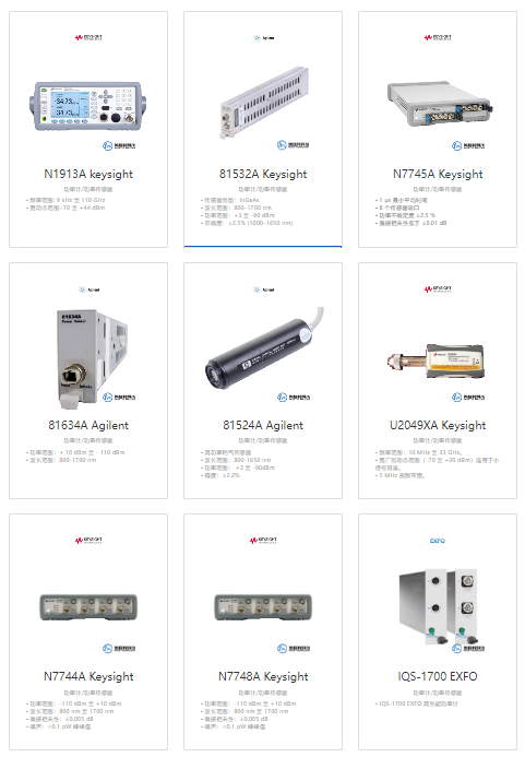
- Spectrum Analyzer (Spectrum Analyzer): Used to measure the frequency of electromagnetic waves, also known as the rate of oscillation. The Spectrum Analyzer shows whether the spectrum is as expected.
- Vector Signal Analyzer (Vector Signal Analyzer): Used to measure the modulation method, also known as the coding method. The Vector Signal Analyzer displays modulation quality indicators such as error vector magnitude, phase error, constellation diagram, etc.
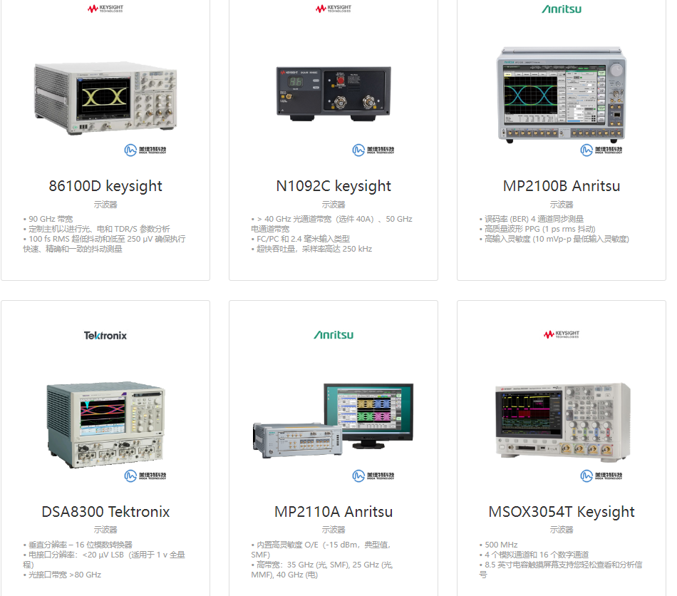
- Bit Error Rate Tester (BERT): Used to measure the probability of error when the receiver restores the information signal, that is, the degree of distortion. The Bit Error Rate Tester shows whether the BER is as expected.
- High and low temperature box (High and Low Temperature Box): used to carry out high and low temperature aging test, check product stability. High and low temperature box can simulate different temperature environments, observe whether the product performance is affected.
- Switch: Used for switch testing to check product compatibility. Switch can be connected to different brands of optical modules, to observe whether it can work properly.
- Fiber End Face Detector (Fiber End Face Detector): Used for end face detection to keep the port clean and ensure quality. The Fiber End Face Detector can magnify the image of the fibre end face to check whether there are defects such as dirt or scratches.
Optical module is a device that converts electrical signals into optical signals or optical signals into electrical signals, and it plays an important role in optical communication system. In order to ensure the normal operation of the optical module, we need to test its performance and detect whether it meets the relevant standards and specifications. So, how to test the performance of optical modules? This article will introduce you to some commonly used optical module test methods and test and measurement equipment.
First, the optical module test methods
Optical module test methods are mainly divided into two categories: static test and dynamic test. Static test refers to the optical module does not work, some of its basic parameters of the measurement, such as appearance, size, interface, labels and so on. Dynamic testing refers to the measurement of some performance parameters of the optical module when it is working, such as operating temperature, operating voltage, operating current, transmitting and receiving optical power, eye diagram, wavelength, dispersion and so on.
Static test: Static test is a preliminary screening and inspection of the optical module, mainly including the following aspects:
- Appearance inspection: Check whether the optical module has obvious damage, stains, scratches and other defects, whether there are loose or detached parts, whether there is rust or oxidation.
- Dimensional inspection: Check whether the optical module meets the specified dimensional requirements, such as length, width, height, etc., and whether it matches the corresponding interface.
- Interface check: Check whether the optical module has the correct interface type, such as LC, SC, FC, etc., whether it is clearly labelled, and whether it has a dust cover or protective sleeve.
- Label check: Check whether the optical module has complete label information, such as model number, serial number, production date, manufacturer's name, etc., and whether it is consistent with the actual product.
- Dynamic testing: Dynamic testing is a detailed performance evaluation of the optical module, mainly including the following aspects:
- Operating temperature: the operating temperature is the temperature range of the optical module in normal operation, it will affect the stability and reliability of the optical module. Generally speaking, the higher the operating temperature, the greater the attenuation of the optical module and the shorter its life. Therefore, we need to use a thermometer or temperature sensor to measure the working temperature of the optical module and compare it with the specified temperature range.
- Working Voltage: The working voltage is the voltage value required by the optical module in normal operation, which will affect the output power and sensitivity of the optical module. Generally speaking, the lower the operating voltage, the lower the output power of the optical module and the lower the sensitivity. Therefore, we need to use a voltmeter or voltage sensor to measure the working voltage of the optical module and compare it with the specified voltage range.
- Working current: Working current is the value of current required by the optical module in normal operation, which will affect the heat generation and power consumption of the optical module. Generally speaking, the higher the working current is, the higher the heat generation and the higher the power consumption of the optical module. Therefore, we need to use an ammeter or current sensor to measure the working current of the optical module and compare it with the specified current range.
- Transmitted optical power: Transmitted optical power refers to the power value of the optical signal output from the transmitting end of the optical module, which will affect the transmission distance and signal-to-noise ratio of the optical module. Generally speaking, the higher the transmitted optical power, the longer the transmission distance of the optical module and the higher the signal-to-noise ratio. Therefore, we need to use an optical power meter or optical power sensor to measure the transmitted optical power of the optical module and compare it with the specified power range.
- Received optical power: The received optical power is the power value of the optical signal input from the receiving end of the optical module, which will affect the sensitivity and BER of the optical module. Generally speaking, the higher the received optical power, the higher the sensitivity of the optical module and the lower the BER. Therefore, we need to use an optical power meter or optical power sensor to measure the received optical power of the optical module and compare it with the specified power range.
- Eye Diagram: An eye diagram is a graphical tool used to assess the quality of a digital signal, which shows characteristics such as amplitude, width, rise time, fall time, overlap, jitter, etc. The eye diagram is a graphical tool used to assess the quality of a digital signal. Generally speaking, the more open the eye diagram is, the better the signal quality is. Therefore, we need to use an eye chart meter or eye chart software to measure the eye chart of the optical module and compare it with the specified eye chart standard.
- Wavelength: Wavelength refers to the colour or frequency of the light signal, which affects the transmission rate and dispersion of the optical module. Generally speaking, the shorter the wavelength is, the higher the transmission rate of the optical module and the lower the colour dispersion. Therefore, we need to use a wavelength meter or wavelength sensor to measure the wavelength of the optical module and compare it with the specified wavelength range.
- Chromatic dispersion: Chromatic dispersion refers to the phase difference or time delay difference between optical signals of different wavelengths during transmission, which affects the signal distortion and BER of the optical module. Generally speaking, the larger the dispersion, the more serious the signal distortion and the higher the BER. Therefore, we need to use a dispersion meter or dispersion software to measure the dispersion of the optical module and compare it with the specified dispersion range.
Recommended equipment for testing TX RX optical modules
- Power Meter: Used to measure the power, i.e. the amount of energy, of the electromagnetic wave output from a transmitter. The Power Meter shows whether the output power is as expected.
- Spectrum Analyzer (Spectrum Analyzer): Used to measure the frequency of electromagnetic waves, also known as the rate of oscillation. The Spectrum Analyzer shows whether the spectrum is as expected.
- Vector Signal Analyzer (Vector Signal Analyzer): Used to measure the modulation method, also known as the coding method. The Vector Signal Analyzer displays modulation quality indicators such as error vector magnitude, phase error, constellation diagram, etc.
- Bit Error Rate Tester (BERT): Used to measure the probability of error when the receiver restores the information signal, that is, the degree of distortion. The Bit Error Rate Tester shows whether the BER is as expected.
- High and low temperature box (High and Low Temperature Box): used to carry out high and low temperature aging test, check product stability. High and low temperature box can simulate different temperature environments, observe whether the product performance is affected.
- Switch: Used for switch testing to check product compatibility. Switch can be connected to different brands of optical modules, to observe whether it can work properly.
- Fiber End Face Detector (Fiber End Face Detector): Used for end face detection to keep the port clean and ensure quality. The Fiber End Face Detector can magnify the image of the fibre end face to check whether there are defects such as dirt or scratches.