


What are the considerations for actual oscilloscope testing?


Oscilloscope is a commonly used electronic test instrument, which can display and measure the waveform, amplitude, frequency, phase and other parameters of a signal. However, to use an oscilloscope correctly, not only to understand its functions and operating methods, but also to pay attention to some details and techniques in the actual test. In this article, we will introduce some of the oscilloscope actual test considerations, hope to help electronic engineers.
Choosing the right probe
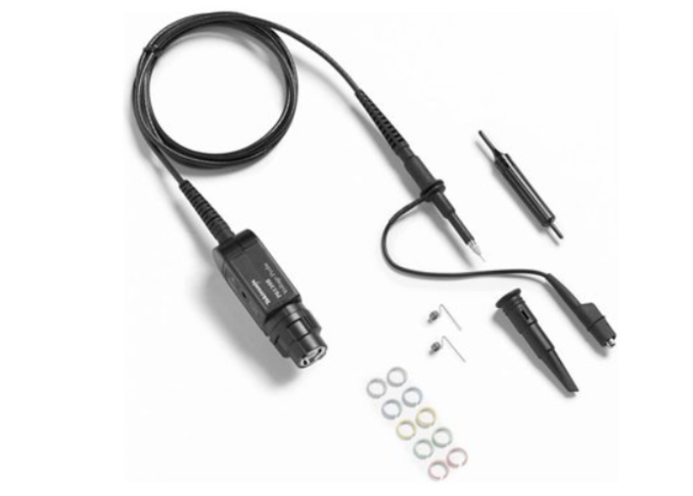
The probe is the interface between the oscilloscope and the circuit under test, and its performance and quality directly affect the accuracy of the measurement results. There are different types and parameters of probes, such as passive probes, active probes, differential probes, current probes, etc., which have their own advantages, disadvantages and scope of application. When selecting a probe, the following factors should be considered:
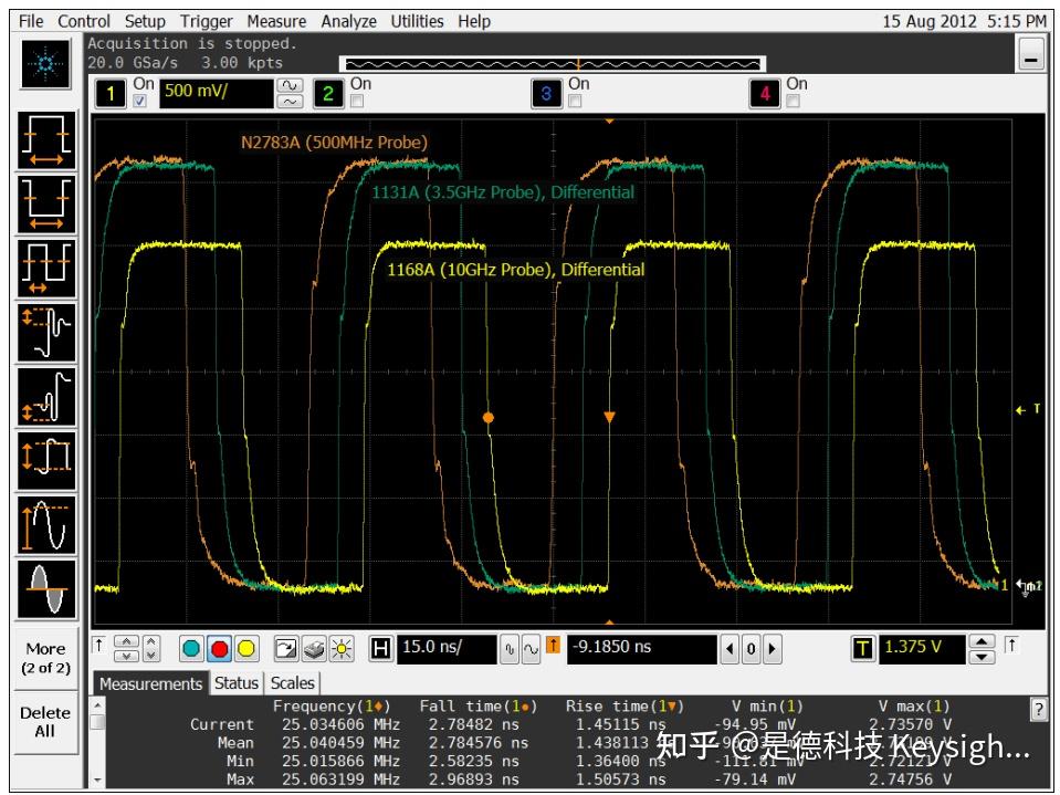
- The bandwidth of the probe should be greater than or equal to the bandwidth of the oscilloscope to avoid signal distortion or attenuation.
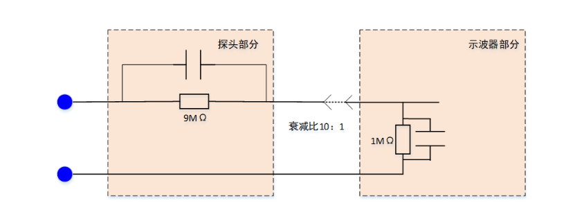
- The input impedance of the probe should be as high as possible to minimise the effect of the load on the circuit under test.
- The attenuation ratio of the probe should be matched with the oscilloscope to ensure the correct display of the signal amplitude.
- The type of probe should be selected according to the characteristics of the signal under test, such as single-ended probes for single-ended signals, differential probes for differential signals, active probes for high-frequency signals, and current probes for high-current signals.
Calibrating and Compensating Probes
Before using a probe, calibrate and compensate it to ensure impedance matching and consistent frequency response between the probe and the oscilloscope. Calibrate and compensate by:
- Connect the probe to the oscilloscope and select the same attenuation ratio as the probe.
- Hook the probe to the output of the square wave calibration signal provided on the oscilloscope and clamp the grounding clip to the ground.
- Adjust the vertical and horizontal stops of the oscilloscope so that the square wave signal occupies most of the screen area.
- Observe whether the rising and falling edges of the square wave signal are smooth, symmetrical and free of overshoot. If not, adjust the compensation capacitor knob on the probe until the square wave signal presents a desirable state.
Setting a reasonable trigger
Triggering is the key for the oscilloscope to capture and display stable waveforms. Triggering can be based on different conditions to trigger the oscilloscope to start sampling and displaying the signal. There are several types of triggering:
- Edge triggering: triggered according to the rising or falling edge of the signal passing through a certain level.
- Pulse Trigger: Trigger according to the signal duration greater or less than a certain set value.
- Slope Trigger: Triggered according to the rising or falling rate of the signal which is greater or less than a certain set value.
- Video Trigger: Trigger according to the line sync or field sync pulse in the video signal.
- Bus Trigger: Trigger according to the specific data or address in the bus signal.
When setting the trigger, pay attention to the following points:
- Select the appropriate trigger type to suit the characteristics of the signal under test.
- Adjust the reasonable trigger level to avoid false trigger or missed trigger.
- Adjust the appropriate trigger sensitivity to suppress the influence of noise or interference.
- Adjust the appropriate trigger delay to observe the leading or trailing edge of the signal.
Choosing the right sampling rate and storage depth
Sampling rate is the number of samples per second of the oscilloscope, which determines the ability of the oscilloscope to capture signal details. The storage depth is the maximum number of samples that can be stored in each channel of the oscilloscope, which determines the ability of the oscilloscope to record the signal history. When selecting the sampling rate and storage depth, pay attention to the following points:
- The sampling rate should satisfy Nyquist's theorem, i.e., it should be at least greater than twice the highest frequency of the measured signal to avoid aliasing.
- The sampling rate should be selected according to the rise time of the measured signal, and the number of sampling points is generally required to be greater than or equal to 10 times of the rise time of the signal, in order to ensure the restoration of the signal waveform.
- The storage depth should be selected according to the repetition frequency and duration of the measured signal, and the storage depth is generally required to be greater than or equal to the product of the signal period and the sampling rate, in order to ensure the completeness of the signal period.
- The storage depth should also be selected according to the details of the signal to be observed. Generally, the larger the storage depth, the higher the resolution, and the more details of the signal can be displayed.
Using the automatic measurement and analysis functions of oscilloscopes
Modern oscilloscopes are equipped with powerful automatic measurement and analysis functions, which can measure and calculate various parameters of the signal, such as amplitude, frequency, period, phase, duty cycle, pulse width, rise time, fall time, maximum value, minimum value, average value, RMS value, peak-to-peak value, etc. These functions help the user to quickly obtain the characteristics and status of a signal without the need to make measurements or calculations manually. When using the automatic measurement and analysis functions, pay attention to the following points:
- Select the appropriate measurement object and method, such as single channel or multiple channels, full screen or cursor area, etc.
- Select suitable measurement parameters and quantities, such as commonly used parameters or customised parameters, single parameter or multiple parameters, etc.
- Select the appropriate measurement mode and display mode, such as real-time mode or statistical mode, digital display or graphic display, etc.
Oscilloscope is a very useful electronic test instrument, but to use it correctly, you need to master some precautions and techniques in actual testing. This article is just a simple introduction to some of the basic content, more content still need to be users in practice to continue to learn and explore. I hope this article can inspire and help you.
Oscilloscope is a commonly used electronic test instrument, which can display and measure the waveform, amplitude, frequency, phase and other parameters of a signal. However, to use an oscilloscope correctly, not only to understand its functions and operating methods, but also to pay attention to some details and techniques in the actual test. In this article, we will introduce some of the oscilloscope actual test considerations, hope to help electronic engineers.
Choosing the right probe
The probe is the interface between the oscilloscope and the circuit under test, and its performance and quality directly affect the accuracy of the measurement results. There are different types and parameters of probes, such as passive probes, active probes, differential probes, current probes, etc., which have their own advantages, disadvantages and scope of application. When selecting a probe, the following factors should be considered:
- The bandwidth of the probe should be greater than or equal to the bandwidth of the oscilloscope to avoid signal distortion or attenuation.
- The input impedance of the probe should be as high as possible to minimise the effect of the load on the circuit under test.
- The attenuation ratio of the probe should be matched with the oscilloscope to ensure the correct display of the signal amplitude.
- The type of probe should be selected according to the characteristics of the signal under test, such as single-ended probes for single-ended signals, differential probes for differential signals, active probes for high-frequency signals, and current probes for high-current signals.
Calibrating and Compensating Probes
Before using a probe, calibrate and compensate it to ensure impedance matching and consistent frequency response between the probe and the oscilloscope. Calibrate and compensate by:
- Connect the probe to the oscilloscope and select the same attenuation ratio as the probe.
- Hook the probe to the output of the square wave calibration signal provided on the oscilloscope and clamp the grounding clip to the ground.
- Adjust the vertical and horizontal stops of the oscilloscope so that the square wave signal occupies most of the screen area.
- Observe whether the rising and falling edges of the square wave signal are smooth, symmetrical and free of overshoot. If not, adjust the compensation capacitor knob on the probe until the square wave signal presents a desirable state.
Setting a reasonable trigger
Triggering is the key for the oscilloscope to capture and display stable waveforms. Triggering can be based on different conditions to trigger the oscilloscope to start sampling and displaying the signal. There are several types of triggering:
- Edge triggering: triggered according to the rising or falling edge of the signal passing through a certain level.
- Pulse Trigger: Trigger according to the signal duration greater or less than a certain set value.
- Slope Trigger: Triggered according to the rising or falling rate of the signal which is greater or less than a certain set value.
- Video Trigger: Trigger according to the line sync or field sync pulse in the video signal.
- Bus Trigger: Trigger according to the specific data or address in the bus signal.
When setting the trigger, pay attention to the following points:
- Select the appropriate trigger type to suit the characteristics of the signal under test.
- Adjust the reasonable trigger level to avoid false trigger or missed trigger.
- Adjust the appropriate trigger sensitivity to suppress the influence of noise or interference.
- Adjust the appropriate trigger delay to observe the leading or trailing edge of the signal.
Choosing the right sampling rate and storage depth
Sampling rate is the number of samples per second of the oscilloscope, which determines the ability of the oscilloscope to capture signal details. The storage depth is the maximum number of samples that can be stored in each channel of the oscilloscope, which determines the ability of the oscilloscope to record the signal history. When selecting the sampling rate and storage depth, pay attention to the following points:
- The sampling rate should satisfy Nyquist's theorem, i.e., it should be at least greater than twice the highest frequency of the measured signal to avoid aliasing.
- The sampling rate should be selected according to the rise time of the measured signal, and the number of sampling points is generally required to be greater than or equal to 10 times of the rise time of the signal, in order to ensure the restoration of the signal waveform.
- The storage depth should be selected according to the repetition frequency and duration of the measured signal, and the storage depth is generally required to be greater than or equal to the product of the signal period and the sampling rate, in order to ensure the completeness of the signal period.
- The storage depth should also be selected according to the details of the signal to be observed. Generally, the larger the storage depth, the higher the resolution, and the more details of the signal can be displayed.
Using the automatic measurement and analysis functions of oscilloscopes
Modern oscilloscopes are equipped with powerful automatic measurement and analysis functions, which can measure and calculate various parameters of the signal, such as amplitude, frequency, period, phase, duty cycle, pulse width, rise time, fall time, maximum value, minimum value, average value, RMS value, peak-to-peak value, etc. These functions help the user to quickly obtain the characteristics and status of a signal without the need to make measurements or calculations manually. When using the automatic measurement and analysis functions, pay attention to the following points:
- Select the appropriate measurement object and method, such as single channel or multiple channels, full screen or cursor area, etc.
- Select suitable measurement parameters and quantities, such as commonly used parameters or customised parameters, single parameter or multiple parameters, etc.
- Select the appropriate measurement mode and display mode, such as real-time mode or statistical mode, digital display or graphic display, etc.
Oscilloscope is a very useful electronic test instrument, but to use it correctly, you need to master some precautions and techniques in actual testing. This article is just a simple introduction to some of the basic content, more content still need to be users in practice to continue to learn and explore. I hope this article can inspire and help you.