


The working principle of analog oscilloscope


The functional block diagram of the analog oscilloscope is shown in the figure. As can be seen from the figure, it is mainly composed of oscilloscope tubes and circuits that provide driving signals for vertical deflection and horizontal deflection.
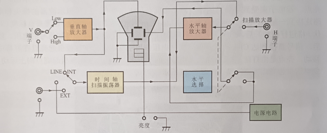
The signal to be observed is added to the vertical input terminal (V terminal) on the panel of the analog oscilloscope, amplified by the vertical axis amplifier, and added to the vertical deflection electrode. At the same time, a horizontal scanning voltage generation circuit is provided in the inside of the analog oscilloscope, and the generated horizontal scanning sawtooth voltage is added to the horizontal deflection electrode of the analog oscilloscope tube. This circuit is also known as the time axis scan oscillator circuit.
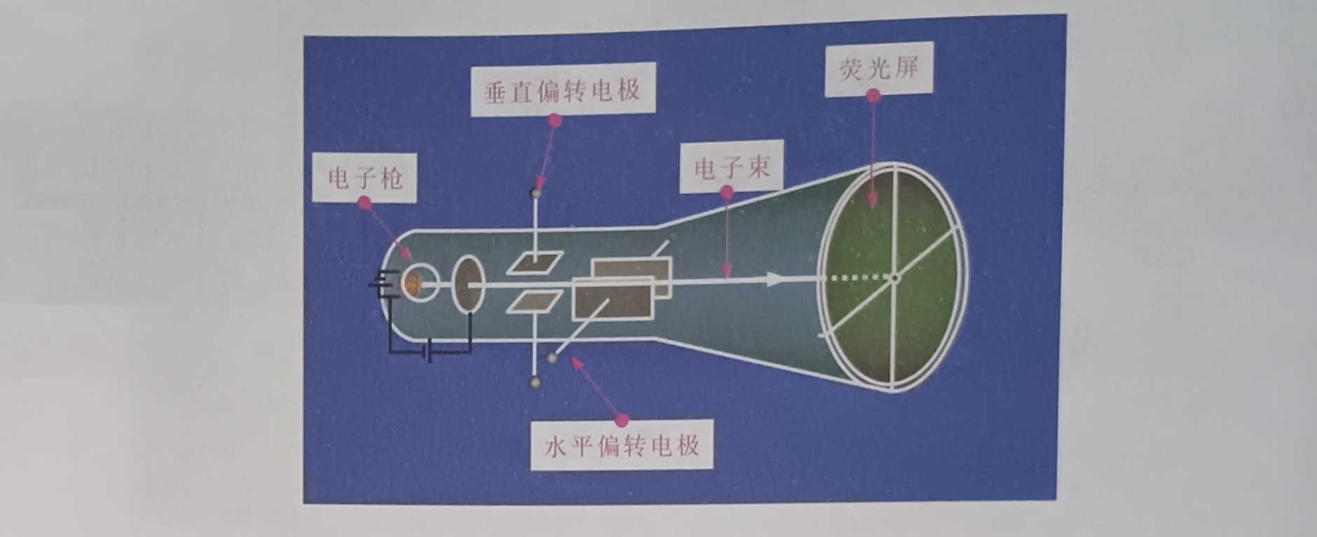
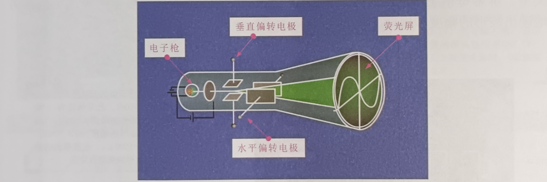
The main device of analog oscilloscope to display signal waveform is oscilloscope tube. Figure 2-25 shows the structure. The oscilloscope tube is actually a picture tube, also called a cathode ray tube (CRT). The front end of the oscilloscope tube is a circular (or square) phosphor screen, coated with phosphor on the inside of the phosphor screen, the oscilloscope tail is provided with an electron gun, when the electron gun is heated by the filament will emit electrons in the direction of the anode, under the action of the phosphor, the electron beam will emit light on the phosphor screen, if it is emitted in the same position on the screen, it will show more and more bright. When the electron gun emits the electron beam according to the input signal.
When the waveform changes, the waveform of the signal can be displayed on the oscilloscope tube. From the structure shown in the figure, it can be seen that there are two sets of deflection electrodes in the oscilloscope tube, one set horizontally and the other set vertically. The scanning oscillation circuit generates sawtooth wave signal and adds it to the vertical deflection plate. The electron beam moves up and down under the action of the sawtooth wave voltage. The measured signal is added to the horizontal deflection plate as an input signal, and the electron beam changes left and right according to the waveform of the signal, so that the full signal is displayed on the screen of the oscilloscope tube.
If the electron beam is not acted on by an external force, the electron beam will shoot into the center of the fluorescent screen, so it shows a bright spot, if the electron beam is acted on by an external force, then it will show a change. After connecting the probe and circuit of the analog oscilloscope together, the voltage signal reaches the vertical deflection system of the analog oscilloscope through the probe. When the vertical scale is set (volts/grid control), the attenuator can reduce the voltage of the signal, while the amplifier can increase the voltage of the signal. The signal then goes directly to the vertical deflection plate of the CRT. Voltage applied to these vertical deflectors causes the bright spots to move across the screen. Bright spots are produced by a beam of electrons hitting the fluorescent material inside the CRT. Positive voltage causes bright spot to move upward and negative voltage causes bright spot to move downward, as shown in the figure.
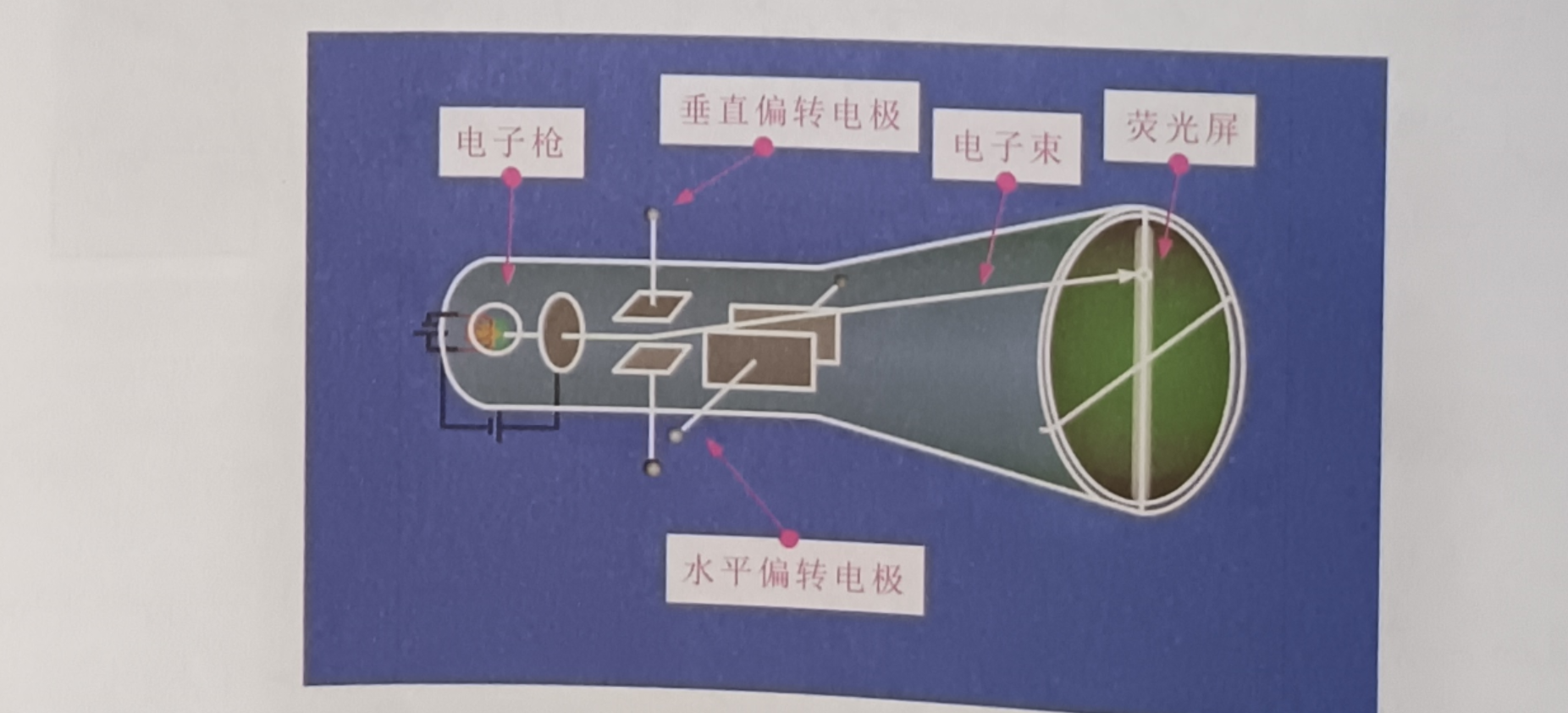
The signal is also triggered by the trigger system activation or triggered horizontal scanning. Horizontal scanning is a system that deflects an electron beam in a horizontal direction. After the horizontal system is triggered, the highlights move from left to right based on the horizontal time base, according to a specific time interval, and the fast-moving highlights fuse together to form a solid line. If the speed is high enough, the number of times that the highlight sweeps through the screen per private clock is as high as 500,000 times, as shown in the figure.
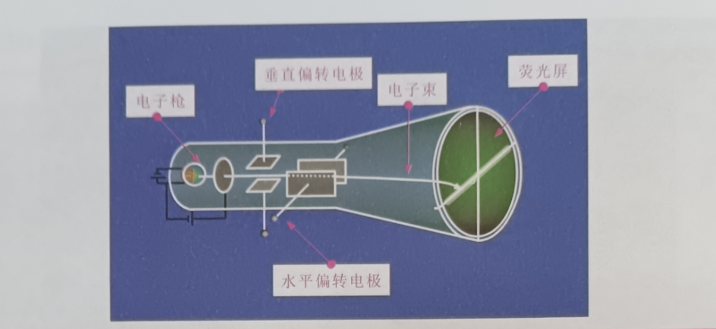
Horizontal scanning and vertical deflection work together to form a signal image displayed on the screen. The trigger stabilizes the repeated signal, ensuring that the scan always starts at the same point of the repeated signal, with the goal of making the rendered image clear, as shown in the figure.
The functional block diagram of the analog oscilloscope is shown in the figure. As can be seen from the figure, it is mainly composed of oscilloscope tubes and circuits that provide driving signals for vertical deflection and horizontal deflection.
The signal to be observed is added to the vertical input terminal (V terminal) on the panel of the analog oscilloscope, amplified by the vertical axis amplifier, and added to the vertical deflection electrode. At the same time, a horizontal scanning voltage generation circuit is provided in the inside of the analog oscilloscope, and the generated horizontal scanning sawtooth voltage is added to the horizontal deflection electrode of the analog oscilloscope tube. This circuit is also known as the time axis scan oscillator circuit.
The main device of analog oscilloscope to display signal waveform is oscilloscope tube. Figure 2-25 shows the structure. The oscilloscope tube is actually a picture tube, also called a cathode ray tube (CRT). The front end of the oscilloscope tube is a circular (or square) phosphor screen, coated with phosphor on the inside of the phosphor screen, the oscilloscope tail is provided with an electron gun, when the electron gun is heated by the filament will emit electrons in the direction of the anode, under the action of the phosphor, the electron beam will emit light on the phosphor screen, if it is emitted in the same position on the screen, it will show more and more bright. When the electron gun emits the electron beam according to the input signal.
When the waveform changes, the waveform of the signal can be displayed on the oscilloscope tube. From the structure shown in the figure, it can be seen that there are two sets of deflection electrodes in the oscilloscope tube, one set horizontally and the other set vertically. The scanning oscillation circuit generates sawtooth wave signal and adds it to the vertical deflection plate. The electron beam moves up and down under the action of the sawtooth wave voltage. The measured signal is added to the horizontal deflection plate as an input signal, and the electron beam changes left and right according to the waveform of the signal, so that the full signal is displayed on the screen of the oscilloscope tube.
If the electron beam is not acted on by an external force, the electron beam will shoot into the center of the fluorescent screen, so it shows a bright spot, if the electron beam is acted on by an external force, then it will show a change. After connecting the probe and circuit of the analog oscilloscope together, the voltage signal reaches the vertical deflection system of the analog oscilloscope through the probe. When the vertical scale is set (volts/grid control), the attenuator can reduce the voltage of the signal, while the amplifier can increase the voltage of the signal. The signal then goes directly to the vertical deflection plate of the CRT. Voltage applied to these vertical deflectors causes the bright spots to move across the screen. Bright spots are produced by a beam of electrons hitting the fluorescent material inside the CRT. Positive voltage causes bright spot to move upward and negative voltage causes bright spot to move downward, as shown in the figure.
The signal is also triggered by the trigger system activation or triggered horizontal scanning. Horizontal scanning is a system that deflects an electron beam in a horizontal direction. After the horizontal system is triggered, the highlights move from left to right based on the horizontal time base, according to a specific time interval, and the fast-moving highlights fuse together to form a solid line. If the speed is high enough, the number of times that the highlight sweeps through the screen per private clock is as high as 500,000 times, as shown in the figure.
Horizontal scanning and vertical deflection work together to form a signal image displayed on the screen. The trigger stabilizes the repeated signal, ensuring that the scan always starts at the same point of the repeated signal, with the goal of making the rendered image clear, as shown in the figure.