


Key button function of analog oscilloscope (2)


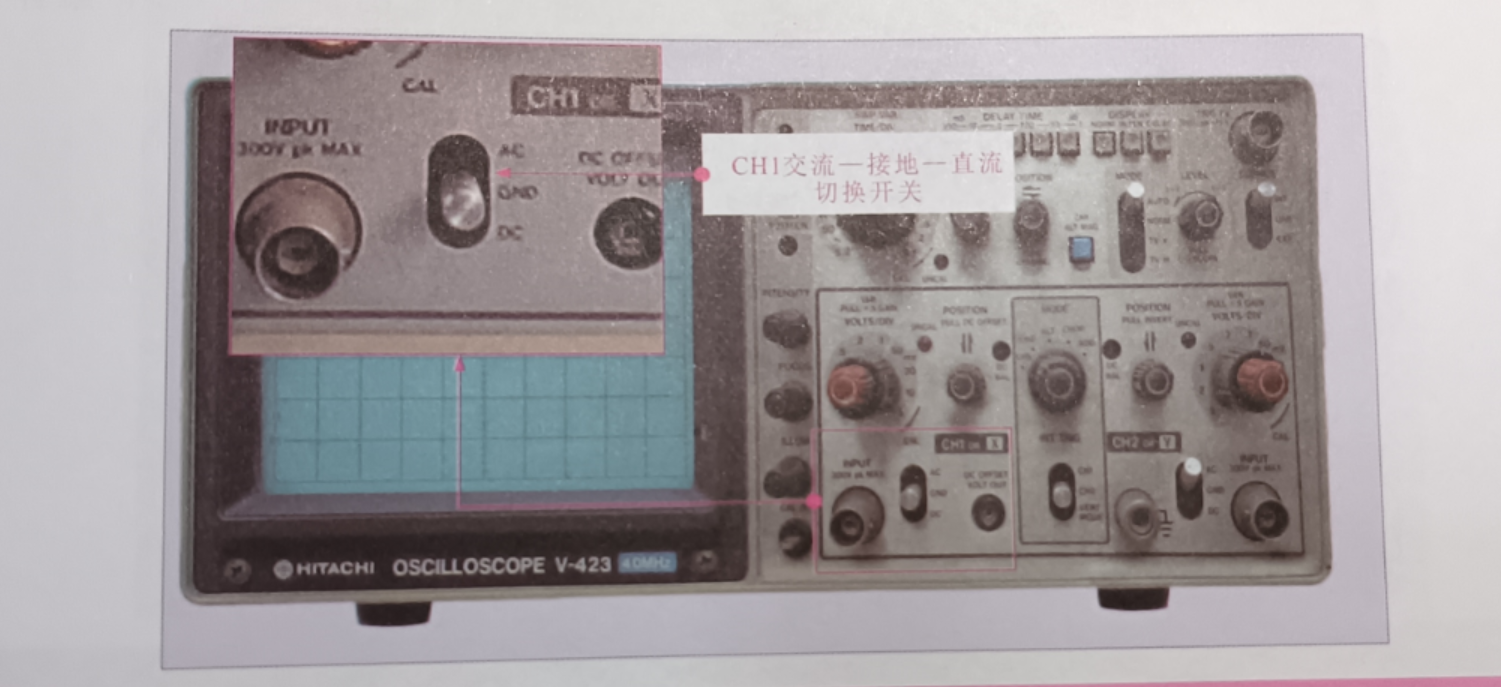
CH1 AC to ground continuous current switch [(CH-I) AC-GNDD-DC]: Select different gear according to the input signal of the CH1 signal input. AC is for observing AC signal, DC is for observing DC signal, and GND is for observing ground, as shown in the figure.
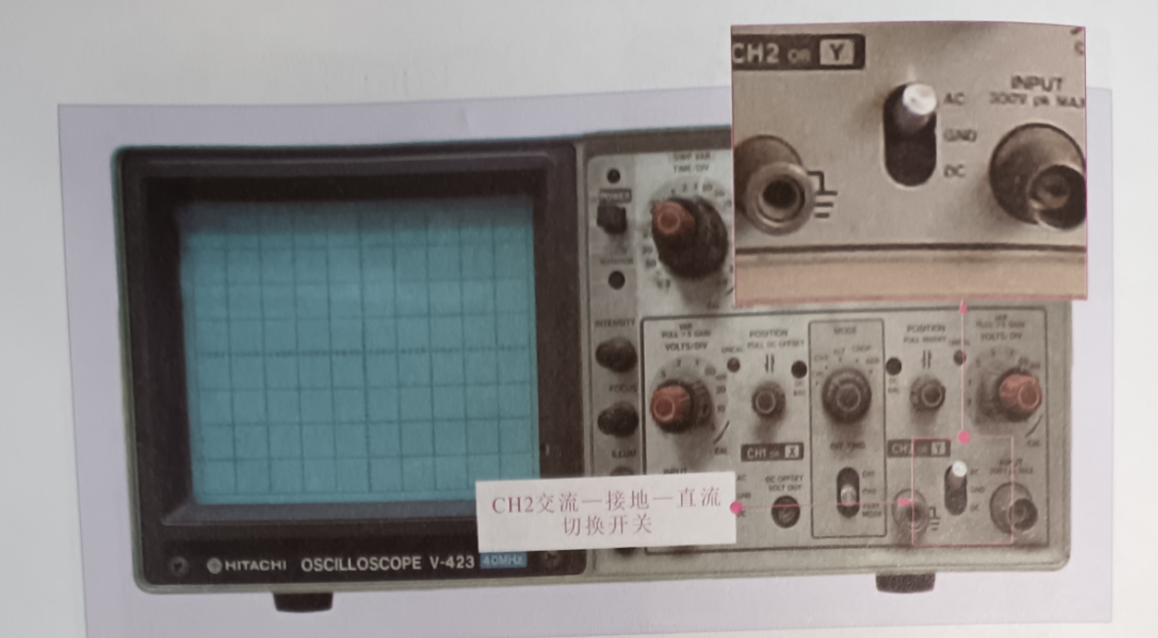
CH2 AC to ground continuous current switch [(CH-2) AC-GNDD-DC]: Select different gear according to the input signal of CH2 signal input. AC is for observing AC signal, DC is for observing DC signal, and GND is for observing ground, as shown in the figure
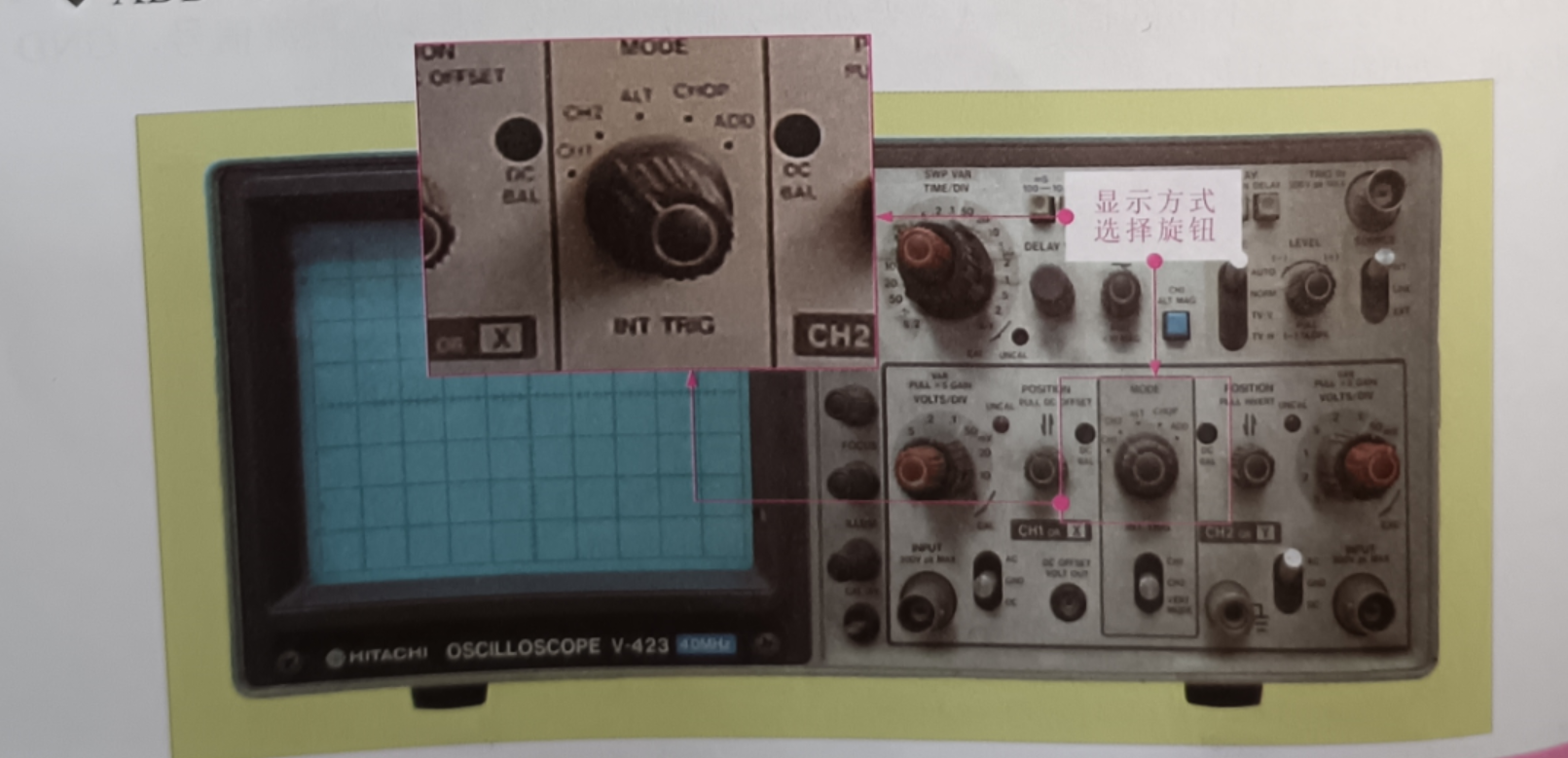
Display MODE knob (MODE): Set five shifts: CH-1, CH-2, CHOP, ALT, and ADD, as shown in Figure 2-13.
CH-1: Displays only the waveform of the input signal from CH-1
CH-2: Displays only the waveform of the input signal from CH-2
CHOP: Quickly switches the display mode.
ALT: The waveforms of the two input signals are displayed alternately.
ADD (Addition): The input signals of CH-1 and CH-2 are added or subtracted and displayed
CHI vertical POSITION PULL DC OFFSETI: Used to adjust the position of the moving waveform for easy observation.
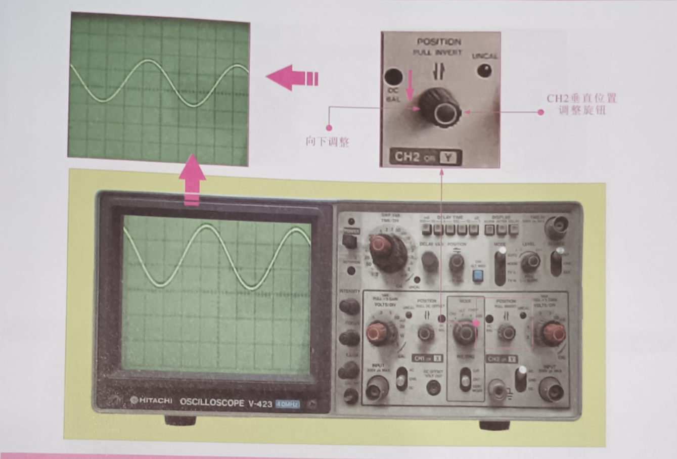
(CH2) POSITION PULLINVERT: Used to move the waveform position appropriately for easy observation, as shown in the figure.
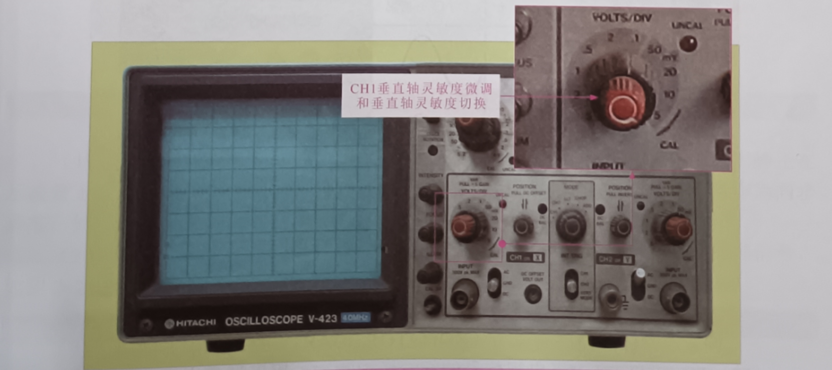
CH1 Vertical axis sensitivity fine-tuning (VARIABLE) and vertical axis sensitivity switching (VOLTSDIV): The two knobs are a concentric adjustment knob, the outer ring knob is a sensitivity switching knob, and the inner circle knob is a fine tuning knob, which can switch the attenuation amount of the input circuit according to the amplitude of the measured signal, so that the displayed waveform has an appropriate size on the oscilloscope tube, as shown in the figure.
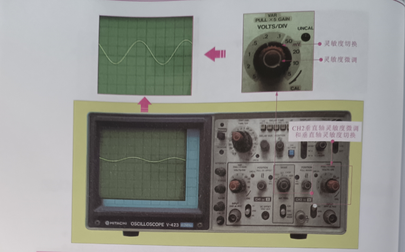
CH2 Vertical Axis Sensitivity Trim (VARIABLE) and Vertical Axis Sensitivity Switch (VOLTS/DIV): Used to adjust the vertical sensitivity of CH2 signal waveform as shown in the figure.
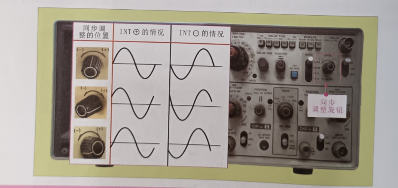
Synchronous adjustment (TRIG LEVEL): Used to fine-tune the frequency or phase of the synchronous signal to match the phase of the measured signal (frequency can be an integer multiple), as shown in the figure.
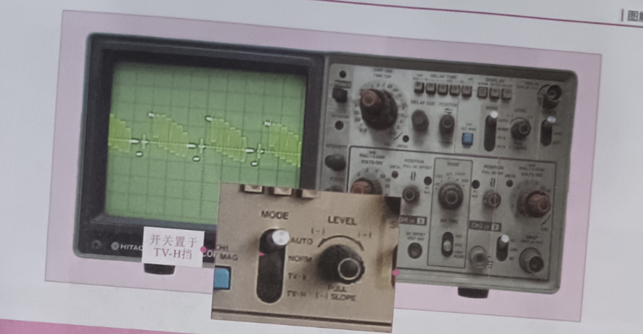
Tv-h and TV-V (Line and field observation of TV signals): Used to adjust line or field observation of TV signals, as shown in the figure.
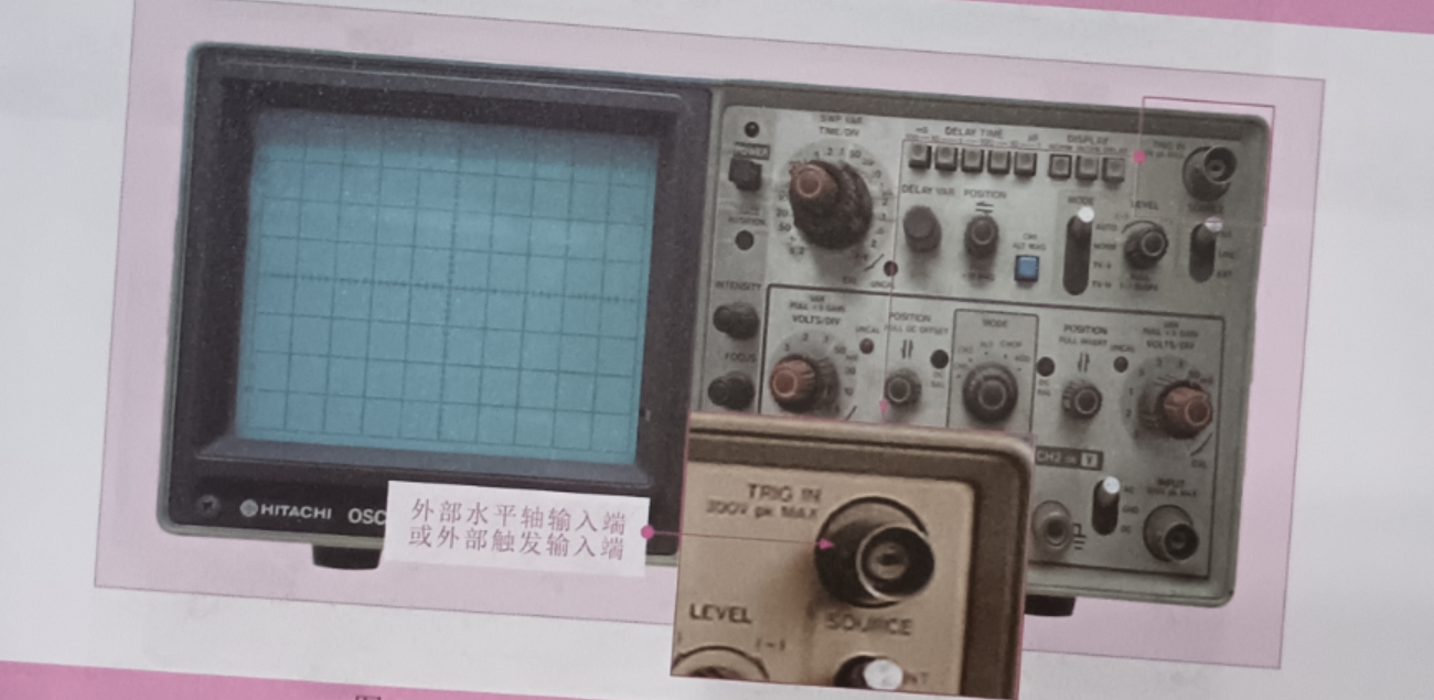
External horizontal axis input or external trigger input (EXT.Hor TRIGN): When the internal scan is synchronized with the external signal, an external synchronization signal is added from this end, as shown in the figure.
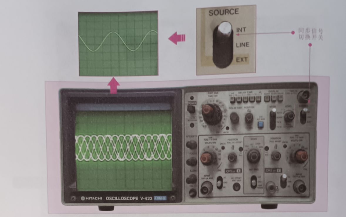
Synchronous (trigger) signal switching switch (TRIG SOURCE): the waveform of the observed signal is stationary on the oscilloscope tube, INT is the internal synchronization source, LINE is the line input signal, EXT is the external input signal as the synchronization reference, as shown in the figure.
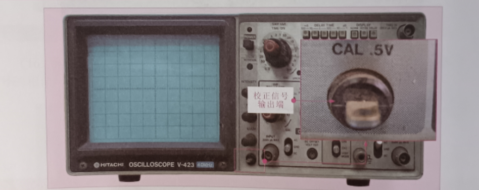
Calibration signal output terminal (CAL.5V): used to output the standard signal generated inside the analog oscilloscope as shown in the figure.
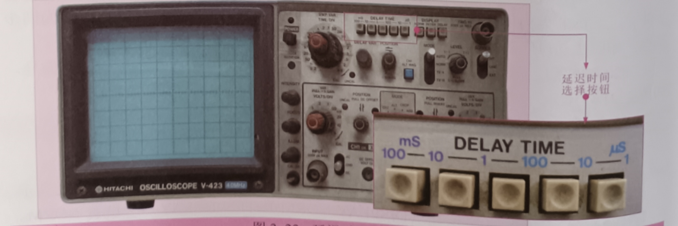
Ground end: When measuring the signal waveform, connect the ground wire to the ground wire of the device under test. TRACE ROTATION: Adjust the horizontal direction of the scan line, internal trigger switch (CH1-CH2 VERTMODE): set the internal trigger mode, delay time select button (DELAYTIME): set 5 delay time gear, as shown in the figure
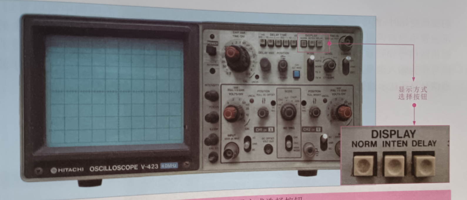
DISPLAY mode select button (DISPLAY NORMINTEN DELAY): Set the NORMINTEN and delay gears, as shown in the figure.
CH1 AC to ground continuous current switch [(CH-I) AC-GNDD-DC]: Select different gear according to the input signal of the CH1 signal input. AC is for observing AC signal, DC is for observing DC signal, and GND is for observing ground, as shown in the figure.
CH2 AC to ground continuous current switch [(CH-2) AC-GNDD-DC]: Select different gear according to the input signal of CH2 signal input. AC is for observing AC signal, DC is for observing DC signal, and GND is for observing ground, as shown in the figure
Display MODE knob (MODE): Set five shifts: CH-1, CH-2, CHOP, ALT, and ADD, as shown in Figure 2-13.
CH-1: Displays only the waveform of the input signal from CH-1
CH-2: Displays only the waveform of the input signal from CH-2
CHOP: Quickly switches the display mode.
ALT: The waveforms of the two input signals are displayed alternately.
ADD (Addition): The input signals of CH-1 and CH-2 are added or subtracted and displayed
CHI vertical POSITION PULL DC OFFSETI: Used to adjust the position of the moving waveform for easy observation.
(CH2) POSITION PULLINVERT: Used to move the waveform position appropriately for easy observation, as shown in the figure.
CH1 Vertical axis sensitivity fine-tuning (VARIABLE) and vertical axis sensitivity switching (VOLTSDIV): The two knobs are a concentric adjustment knob, the outer ring knob is a sensitivity switching knob, and the inner circle knob is a fine tuning knob, which can switch the attenuation amount of the input circuit according to the amplitude of the measured signal, so that the displayed waveform has an appropriate size on the oscilloscope tube, as shown in the figure.
CH2 Vertical Axis Sensitivity Trim (VARIABLE) and Vertical Axis Sensitivity Switch (VOLTS/DIV): Used to adjust the vertical sensitivity of CH2 signal waveform as shown in the figure.
Synchronous adjustment (TRIG LEVEL): Used to fine-tune the frequency or phase of the synchronous signal to match the phase of the measured signal (frequency can be an integer multiple), as shown in the figure.
Tv-h and TV-V (Line and field observation of TV signals): Used to adjust line or field observation of TV signals, as shown in the figure.
External horizontal axis input or external trigger input (EXT.Hor TRIGN): When the internal scan is synchronized with the external signal, an external synchronization signal is added from this end, as shown in the figure.
Synchronous (trigger) signal switching switch (TRIG SOURCE): the waveform of the observed signal is stationary on the oscilloscope tube, INT is the internal synchronization source, LINE is the line input signal, EXT is the external input signal as the synchronization reference, as shown in the figure.
Calibration signal output terminal (CAL.5V): used to output the standard signal generated inside the analog oscilloscope as shown in the figure.
Ground end: When measuring the signal waveform, connect the ground wire to the ground wire of the device under test. TRACE ROTATION: Adjust the horizontal direction of the scan line, internal trigger switch (CH1-CH2 VERTMODE): set the internal trigger mode, delay time select button (DELAYTIME): set 5 delay time gear, as shown in the figure
DISPLAY mode select button (DISPLAY NORMINTEN DELAY): Set the NORMINTEN and delay gears, as shown in the figure.