


Key button function of analog oscilloscope (1)


style="text-wrap: nowrap;">The key button control area of the analog oscilloscope is located on the right side of the entire oscilloscope. Figure 2-4 shows the button control area of a typical analog oscilloscope. Analog oscilloscope operating buttons have their own functions, the following combined with the analog oscilloscope physical drawings are introduced.
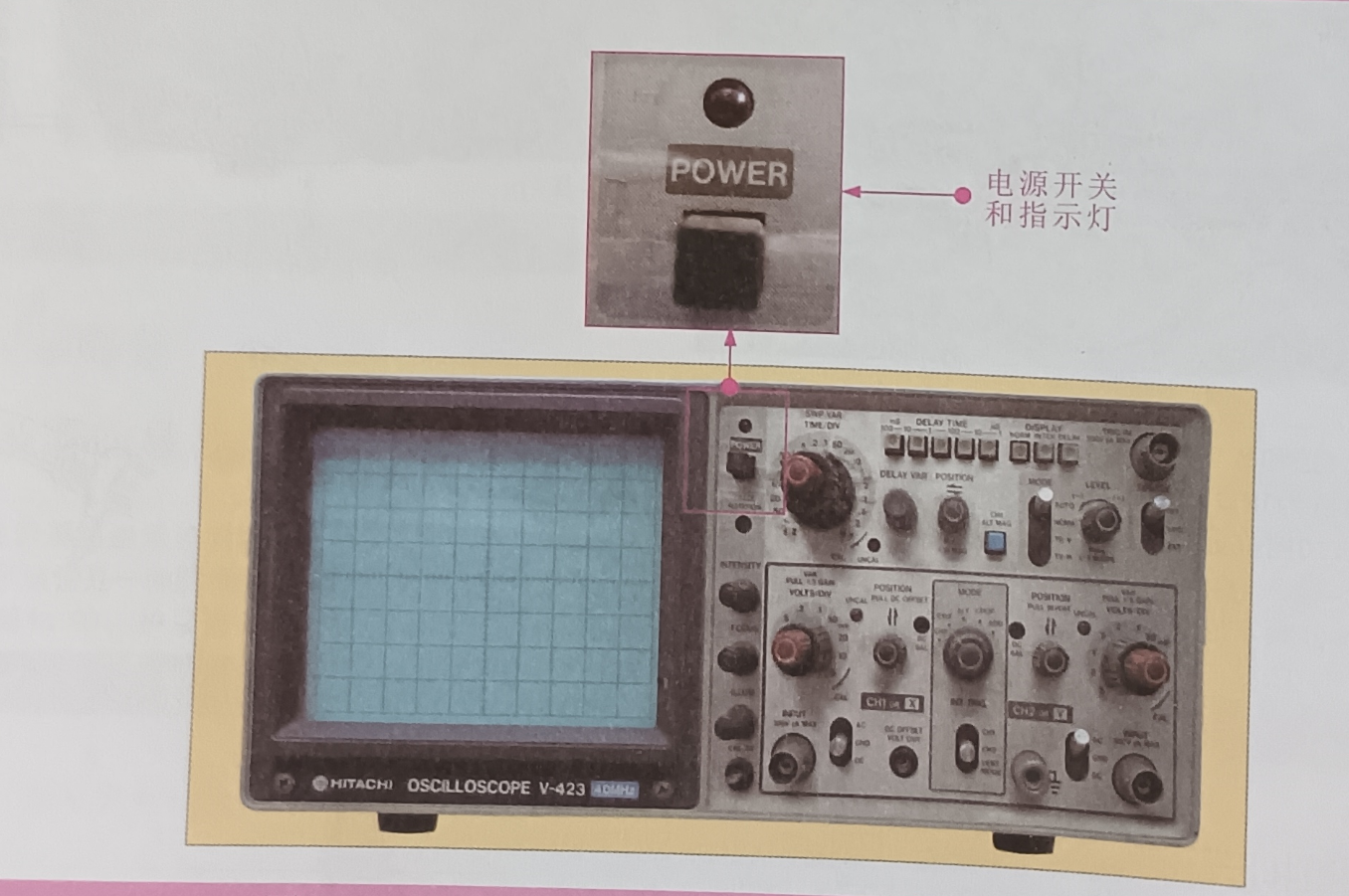
(1) POWER switch: It is used to switch on and off the power supply. When the power supply is switched on, the power indicator above the power switch lights up.
(2) Indicator light: indicates the working status of the oscilloscope. The power switch and indicator light of the analog oscilloscope are shown in the figure.
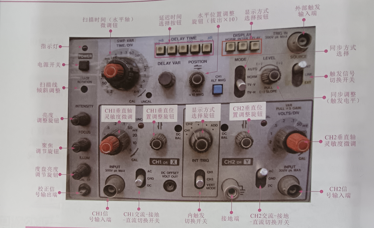
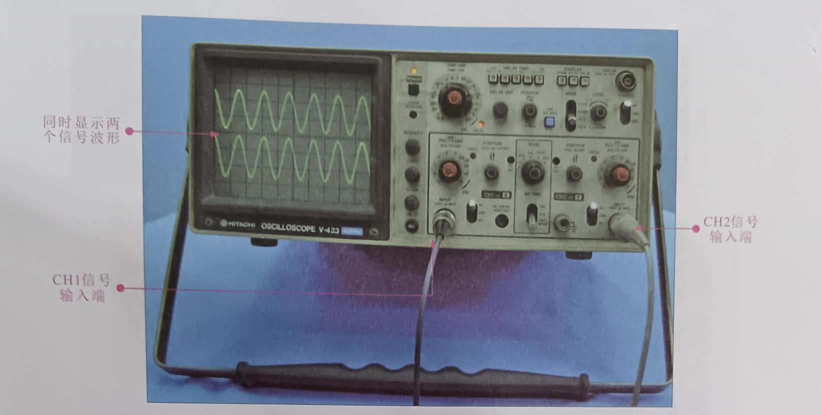
(3)CH1 signal INPUT (INPUT 300V pk MAX): used to connect the oscilloscope CHI test line
(4)CH2 signal INPUT (INPUT 300V pk MAX) : used to connect the oscilloscope CH2 test line. The two input terminals can be used separately or at the same time, as shown in the figure, CHI and CH2 input signal waveforms at the same time.
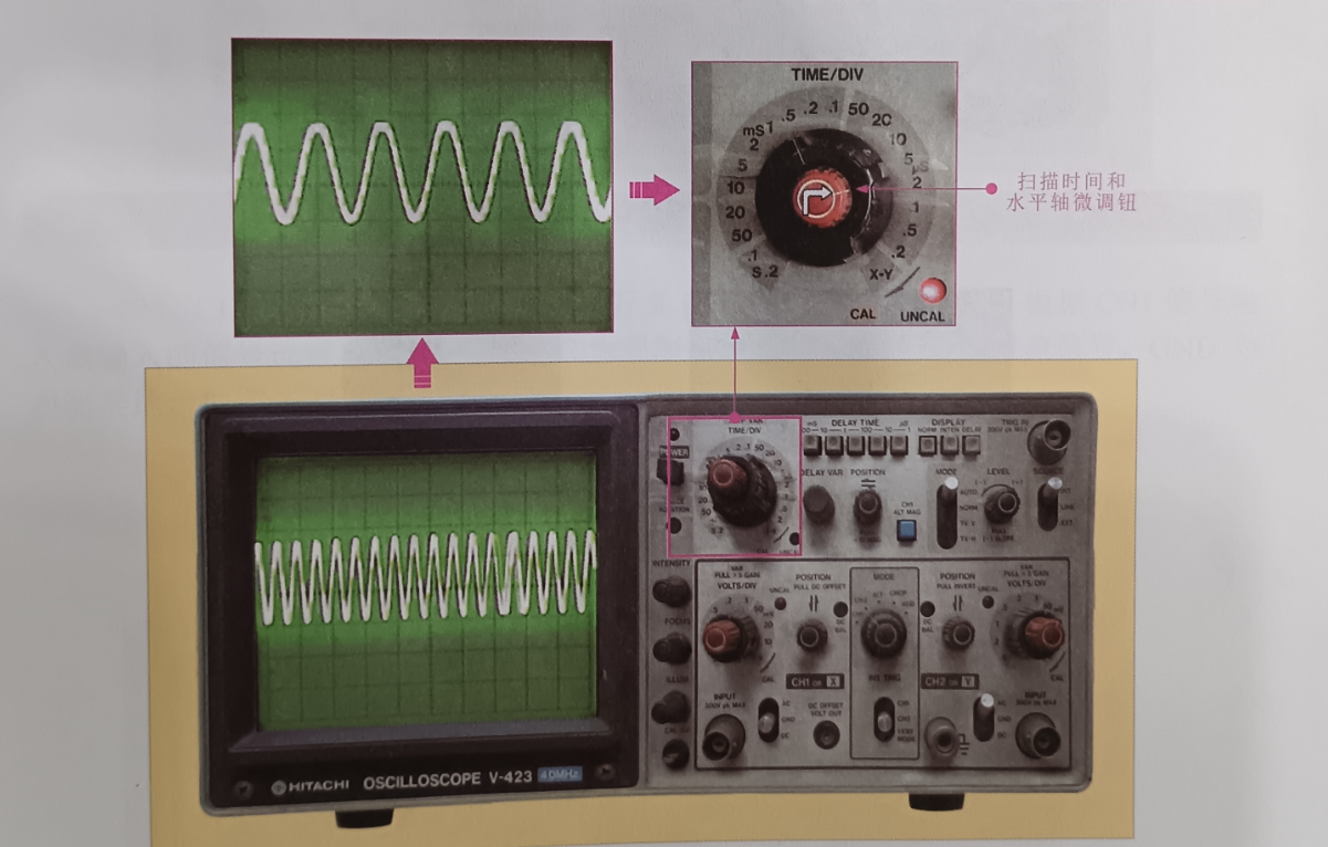
(5) Scanning TIME and horizontal axis fine-tuning button (SWP VAR TIME/DIV is used to adjust the scanning time, as shown in the figure.
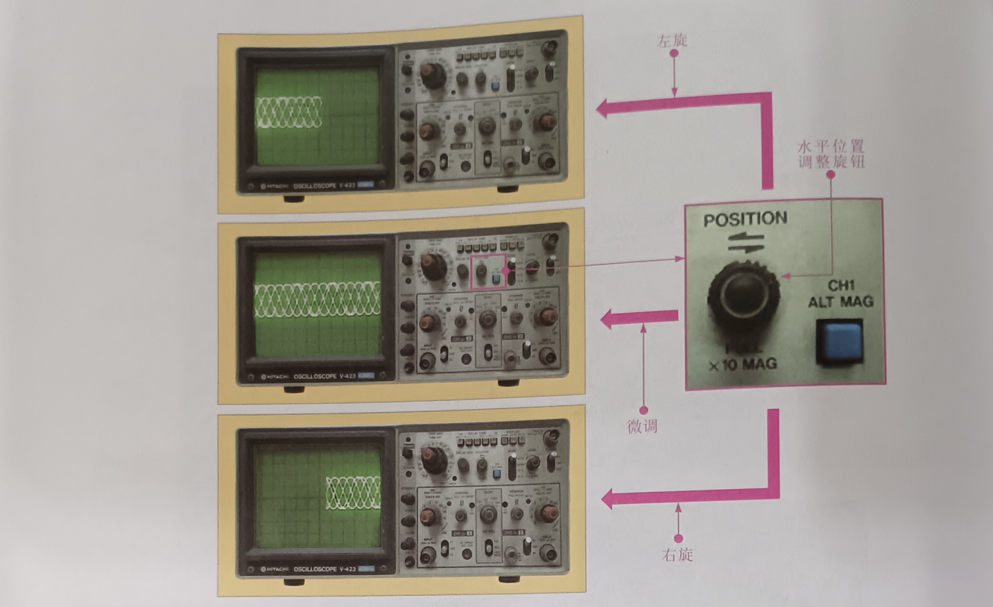
(6) Horizontal POSITION adjustment knob (H POSITION) : used to adjust the horizontal position of the scan line, as shown in the figure.
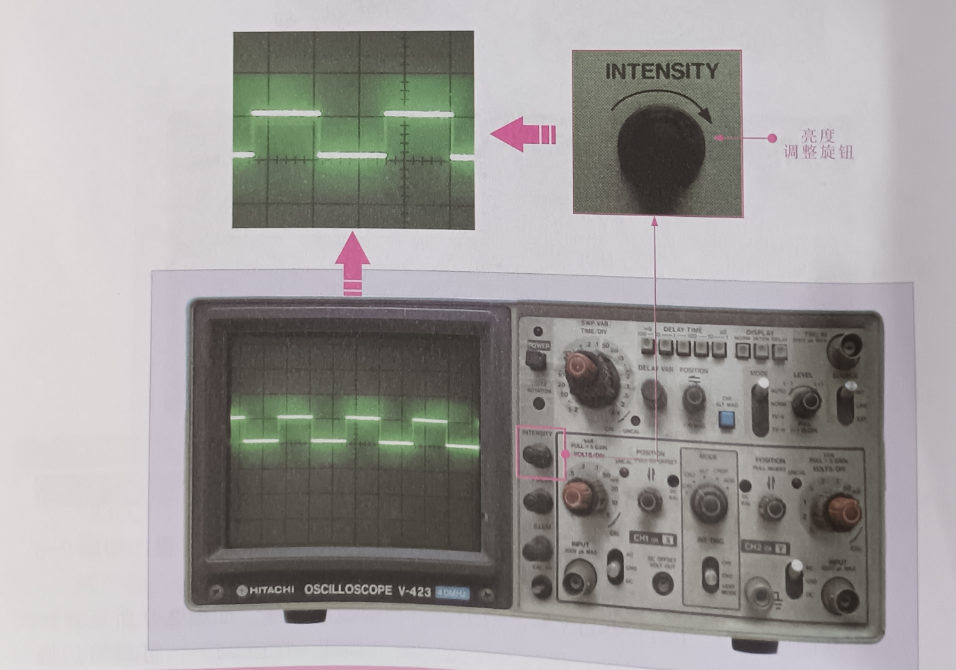
(7) Brightness adjustment knob (INTENSITY) : used to adjust the brightness of the scan line, as shown in the figure.
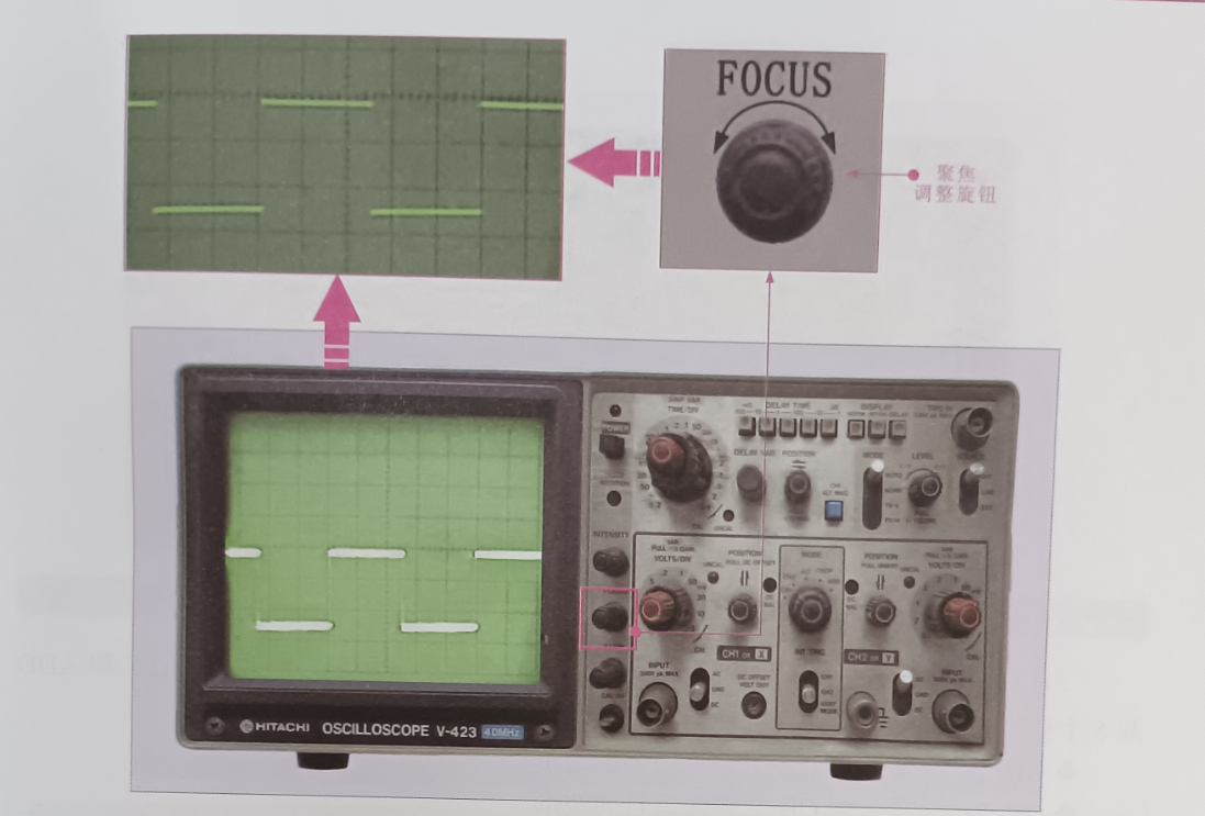
(8) FOCUS adjustment knob (FOCUS) and scan line brightness adjustment (ILLUM) : The scan line can be adjusted to become clearer, as shown in the figure
style="text-wrap: nowrap;">The key button control area of the analog oscilloscope is located on the right side of the entire oscilloscope. Figure 2-4 shows the button control area of a typical analog oscilloscope. Analog oscilloscope operating buttons have their own functions, the following combined with the analog oscilloscope physical drawings are introduced.
(1) POWER switch: It is used to switch on and off the power supply. When the power supply is switched on, the power indicator above the power switch lights up.
(2) Indicator light: indicates the working status of the oscilloscope. The power switch and indicator light of the analog oscilloscope are shown in the figure.
(3)CH1 signal INPUT (INPUT 300V pk MAX): used to connect the oscilloscope CHI test line
(4)CH2 signal INPUT (INPUT 300V pk MAX) : used to connect the oscilloscope CH2 test line. The two input terminals can be used separately or at the same time, as shown in the figure, CHI and CH2 input signal waveforms at the same time.
(5) Scanning TIME and horizontal axis fine-tuning button (SWP VAR TIME/DIV is used to adjust the scanning time, as shown in the figure.
(6) Horizontal POSITION adjustment knob (H POSITION) : used to adjust the horizontal position of the scan line, as shown in the figure.
(7) Brightness adjustment knob (INTENSITY) : used to adjust the brightness of the scan line, as shown in the figure.
(8) FOCUS adjustment knob (FOCUS) and scan line brightness adjustment (ILLUM) : The scan line can be adjusted to become clearer, as shown in the figure