MP2100B BERTWave Ophthalmograph Simple operation instructions
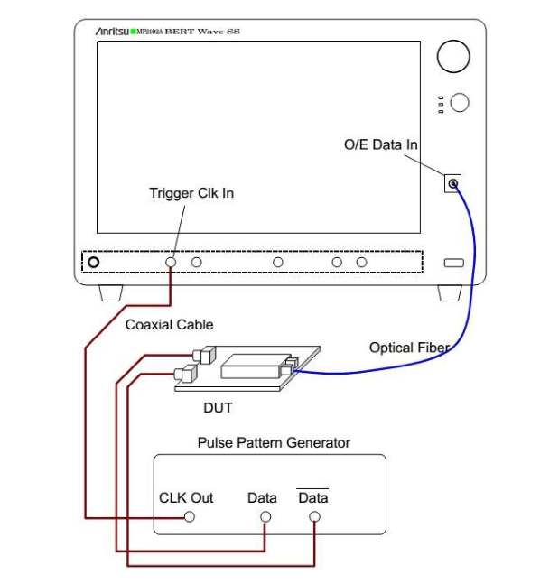
(1) Optical port Settings
The optical power of the input signal can not be too small, otherwise the test effect is not good, and the more appropriate optical power is about -5~-7dBm.
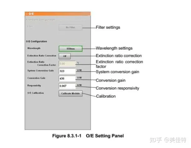
Select O/E on the top menu of the instrument operation interface to open the relevant Settings of optical interface parameters, as shown in the figure. Select Filter,
Wavelength, other values do not need to be set for the time being.
(2) Clock signal related Settings
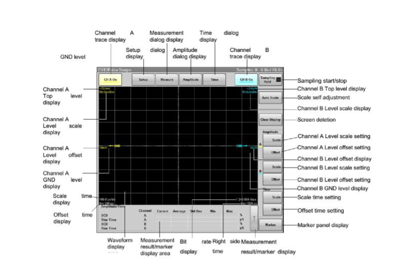
Select EYE/Pulse Scope on the top menu of the instrument operation interface to open the eye map interface, as shown in the figure.
CHA is used to test the electric eye, and CHB is used to test the optical eye, here we only test the optical eye, we need to turn off the CHA,
Confirm that the CHB is enabled. Click on Time in the eye map display window to open the relevant Settings for the clock: determine Bitrate and Divide Ratio.
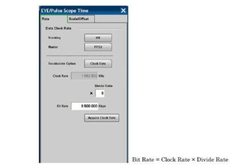
For example, if the eye map of 6G signal is tested, the Bitrate input of 6000000Kbps is 6G, and the Divide Ratio can be modified according to the setting of the error meter (20, 2, etc.).

(3) Parameter test related Settings
In the eye image display window, click Setup to open the Settings of eye image sampling points and limiting factors (time, waveform number).
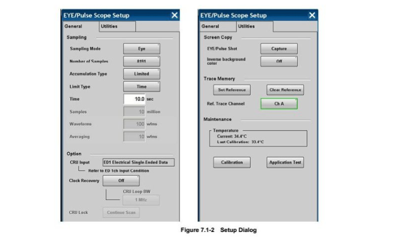
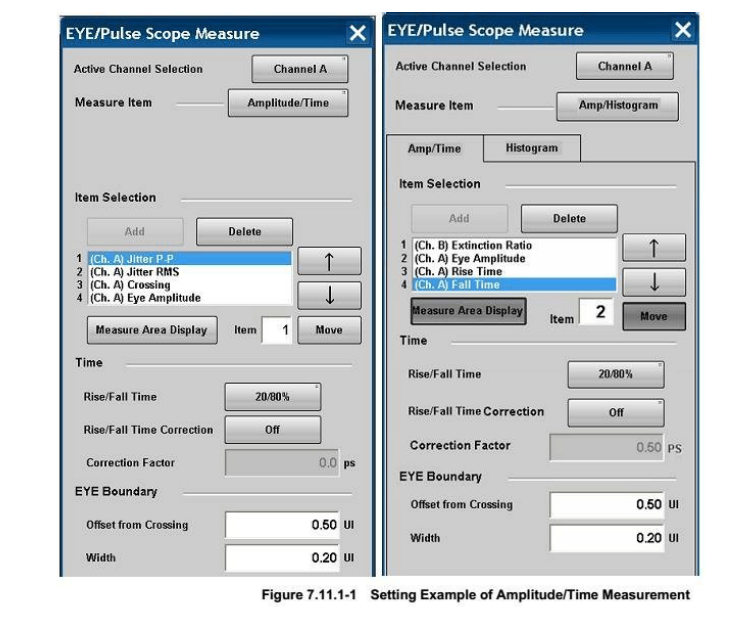
Click Measure in the eye map display window to open the eye map test parameters and eye map template allowance and other related Settings (note that you should select relative to
Channel B).
Calibration instruction
It is best to perform a calibration operation before starting the measurement, which is divided into two parts, as follows:
O/E Calibration: Put the FC cover on (no optical signal can be input), and then perform the calibration Calibration Module, which will be finished after about 5 seconds, as shown in the figure:
Level calibration
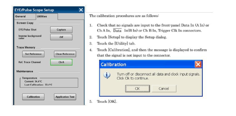
Do not connect any signals on the meter interface (including clock trigger signals), and then select on the menu in the eye map interface
Setup-> Utility-> Calibration Completes calibration.
The BERTWave MP2100B Anritsu is an all-in-one tester with a built-in BERT and sampling oscilloscope to support optical module evaluation, including BER measurements, eye pattern template testing and eye pattern analysis.
BERT and sampling oscilloscopes are essential testers for evaluating optical modules used in optical communication systems. Previously, when evaluating modules such as QSFP+ and SFP+, BERT and sampling oscilloscopes were configured respectively. Now there is the BERTWave MP2100B, whose all-in-one design integrates up to 4 channels of BERT and sampling oscilloscopes in a compact 18-cm deep single cabinet, saving working space.
In addition, when set up with the BERTWave MP2100B Anritsu, BER measurements, eye pattern template tests and eye pattern analysis can be performed simultaneously without changing the connection line, thus reducing the measurement time. Moreover, the BER measurement channels can be extended to four channels, and the 4-channel BER measurement, eye pattern template testing, and eye pattern analysis can be performed simultaneously. Finally, the built-in SFP+ module slot eliminates the need for external light sources.
BERTWave MP2100B Anritsu's BERT measures bit error rate (BER) at bit rates between 125 Mbit/s and 12.5 Gbit/s. Its built-in BERT option of up to 4 channels makes it easy to configure multi-channel optical module test systems such as QSFP+ and AOC. Differential signals support not only bit error rate (BER) measurement, but also eye pattern template testing and eye pattern analysis.

(1) Optical port Settings

The optical power of the input signal can not be too small, otherwise the test effect is not good, and the more appropriate optical power is about -5~-7dBm.
Select O/E on the top menu of the instrument operation interface to open the relevant Settings of optical interface parameters, as shown in the figure. Select Filter,
Wavelength, other values do not need to be set for the time being.
(2) Clock signal related Settings
Select EYE/Pulse Scope on the top menu of the instrument operation interface to open the eye map interface, as shown in the figure.
CHA is used to test the electric eye, and CHB is used to test the optical eye, here we only test the optical eye, we need to turn off the CHA,
Confirm that the CHB is enabled. Click on Time in the eye map display window to open the relevant Settings for the clock: determine Bitrate and Divide Ratio.

For example, if the eye map of 6G signal is tested, the Bitrate input of 6000000Kbps is 6G, and the Divide Ratio can be modified according to the setting of the error meter (20, 2, etc.).

(3) Parameter test related Settings
In the eye image display window, click Setup to open the Settings of eye image sampling points and limiting factors (time, waveform number).

Click Measure in the eye map display window to open the eye map test parameters and eye map template allowance and other related Settings (note that you should select relative to
Channel B).

Calibration instruction
It is best to perform a calibration operation before starting the measurement, which is divided into two parts, as follows:
O/E Calibration: Put the FC cover on (no optical signal can be input), and then perform the calibration Calibration Module, which will be finished after about 5 seconds, as shown in the figure:

Level calibration
Do not connect any signals on the meter interface (including clock trigger signals), and then select on the menu in the eye map interface
Setup-> Utility-> Calibration Completes calibration.

The BERTWave MP2100B Anritsu is an all-in-one tester with a built-in BERT and sampling oscilloscope to support optical module evaluation, including BER measurements, eye pattern template testing and eye pattern analysis.
BERT and sampling oscilloscopes are essential testers for evaluating optical modules used in optical communication systems. Previously, when evaluating modules such as QSFP+ and SFP+, BERT and sampling oscilloscopes were configured respectively. Now there is the BERTWave MP2100B, whose all-in-one design integrates up to 4 channels of BERT and sampling oscilloscopes in a compact 18-cm deep single cabinet, saving working space.
In addition, when set up with the BERTWave MP2100B Anritsu, BER measurements, eye pattern template tests and eye pattern analysis can be performed simultaneously without changing the connection line, thus reducing the measurement time. Moreover, the BER measurement channels can be extended to four channels, and the 4-channel BER measurement, eye pattern template testing, and eye pattern analysis can be performed simultaneously. Finally, the built-in SFP+ module slot eliminates the need for external light sources.
BERTWave MP2100B Anritsu's BERT measures bit error rate (BER) at bit rates between 125 Mbit/s and 12.5 Gbit/s. Its built-in BERT option of up to 4 channels makes it easy to configure multi-channel optical module test systems such as QSFP+ and AOC. Differential signals support not only bit error rate (BER) measurement, but also eye pattern template testing and eye pattern analysis.


