


Equivalent time sampling oscilloscope vs. real-time oscilloscope, what's the difference?


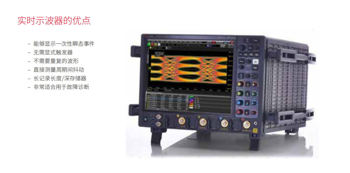
Real-Time Oscilloscopes
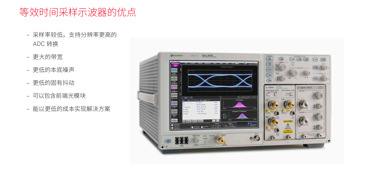
Equivalent Time Sampling Oscilloscopes for ADCs
A real-time oscilloscope, sometimes called a "single-shot" oscilloscope, captures a complete waveform each time it is triggered. In other words, it captures a large number of data points in a continuous record. To better understand this type of data acquisition, think of it as a very fast analog-to-digital converter (ADC) whose sampling rate determines the sample interval and whose memory depth determines the number of points that will be displayed. In order to capture various waveforms, the sampling rate of the ADC needs to be significantly higher than the frequency of the input waveform. This sampling rate can reach up to 256 GSa/s, which determines the bandwidth that now extends to 110 GHz.
Trigger Real-Time Oscilloscopes
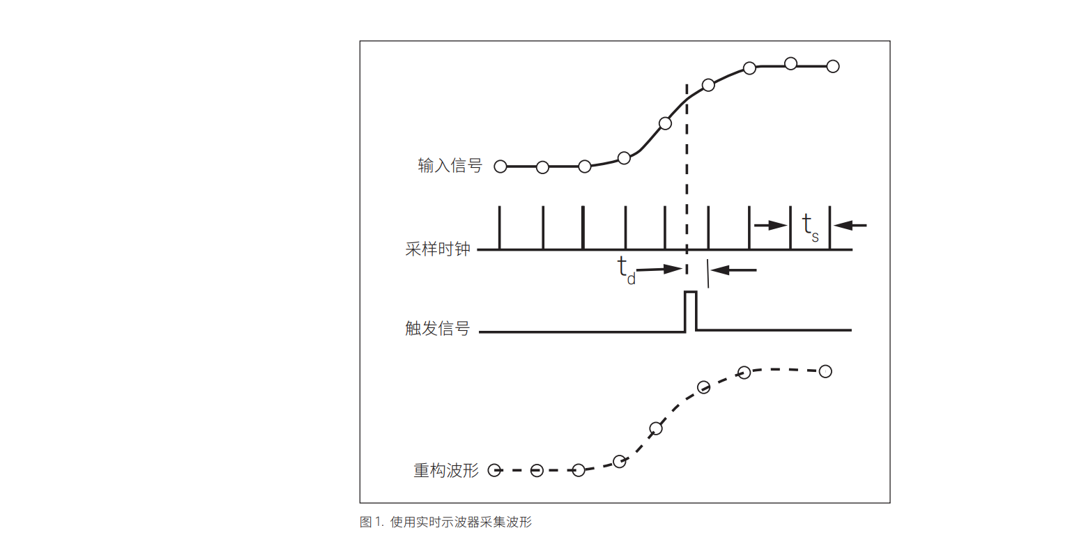
Real-time oscilloscopes can be triggered based on the characteristics of the data itself, usually when the amplitude of the input waveform reaches a certain threshold. At this point, the oscilloscope begins to asynchronously convert the analog waveform to digital data samples at a rate that is independent of the data rate of the input waveform. This conversion rate is called the sample rate and usually comes from the internal clock signal. As shown in Figure 1, the oscilloscope samples the amplitude of the input waveform, saves the sample value to memory, and then proceeds to the next sample. The main task of the trigger is to provide a horizontal time reference point for the input data.
Equivalent Time Sampling Oscilloscope
One sample at a time
An equivalent-time sampling oscilloscope, sometimes referred to as a "sampling oscilloscope," measures only the instantaneous amplitude of the waveform point at the moment of sampling. Unlike a real-time oscilloscope, it only samples the input signal once at each trigger. The oscilloscope adds an hour delay to the next trigger, and then takes the next sample. The number of samples you want to obtain determines the number of waveform periods needed to reproduce the waveform. The measurement bandwidth is determined by the frequency response of the sample head, which can now be extended beyond 80 GHz. There are some very distinct differences in the triggering and subsequent sampling of an equivalent time sampling oscilloscope compared to a real-time oscilloscope.
Sampling Method
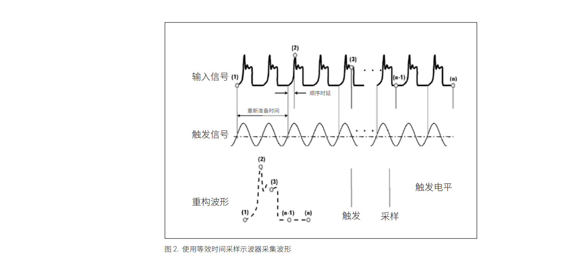
Most importantly, the equivalent time sampling oscilloscope requires an explicit trigger to work, and that trigger needs to be synchronized with the input data. The trigger is usually provided by the user, but in some cases a hardware clock recovery module can be used to obtain the trigger signal. The sampling flow is as follows: a trigger event initiates the acquisition of the first sample, and then the oscilloscope is re-prepared for the next trigger event. The next trigger event initiates the second acquisition and adds a precise incremental delay before sampling the second data point. The size of this incremental delay is determined by the time base setting and the number of points sampled. As shown in Figure 2, this process is repeated until the entire waveform is acquired.
Equivalent Time Sampling Oscilloscope (continued)
Triggering the Equivalent Time Sampling Oscilloscope
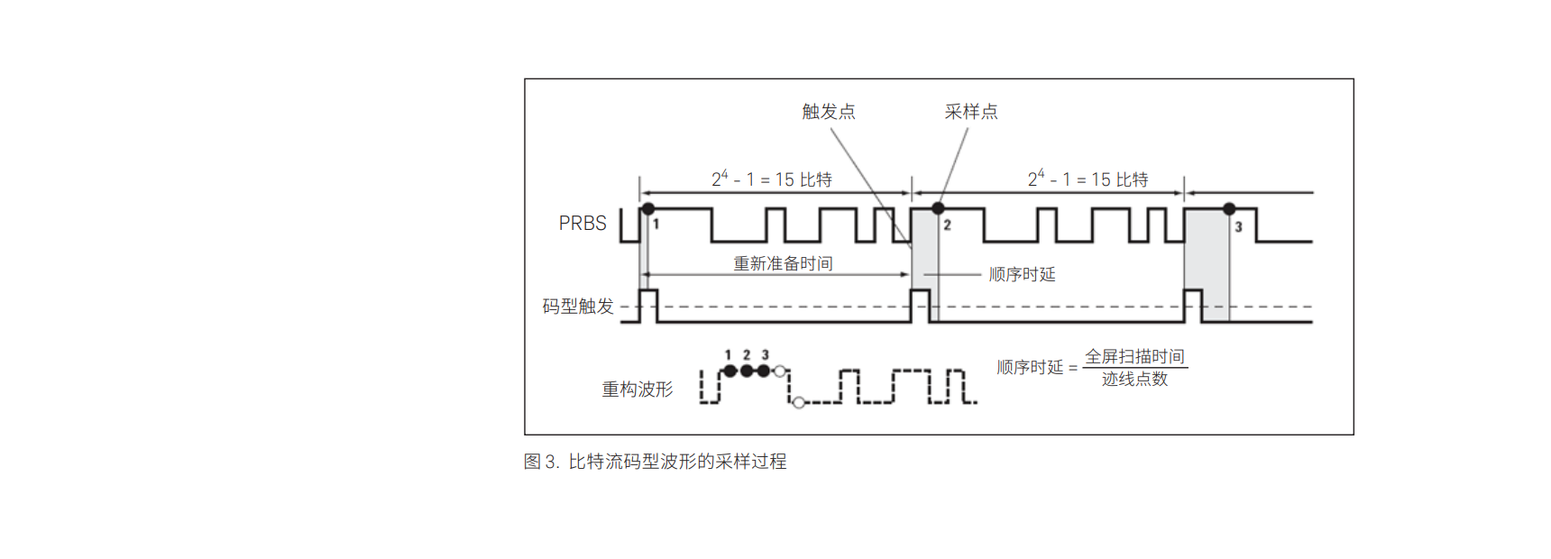
There are two ways to trigger an equivalent time sampling oscilloscope, resulting in two separate data display formats: bitstream or eye diagram. By viewing individual bits of the signal, the user can understand the code pattern dependencies in the system, but high resolution is not allowed when the number of bits is large. To view the bitstream, the trigger can only fire one pulse during the input pattern period and must be in the same relative position in the bit pattern for each event. The oscilloscope then samples the input signal, adds incremental time delays as the next trigger event occurs, and then samples the bitstream until the entire waveform is captured. If you want to view the bitstream on a time-equivalent oscilloscope, you must have a repeating waveform, otherwise you need to use a real-time oscilloscope. The trigger process to display the bitstream waveform is shown in Figure 3.
Eye Diagram
Creating an eye diagram
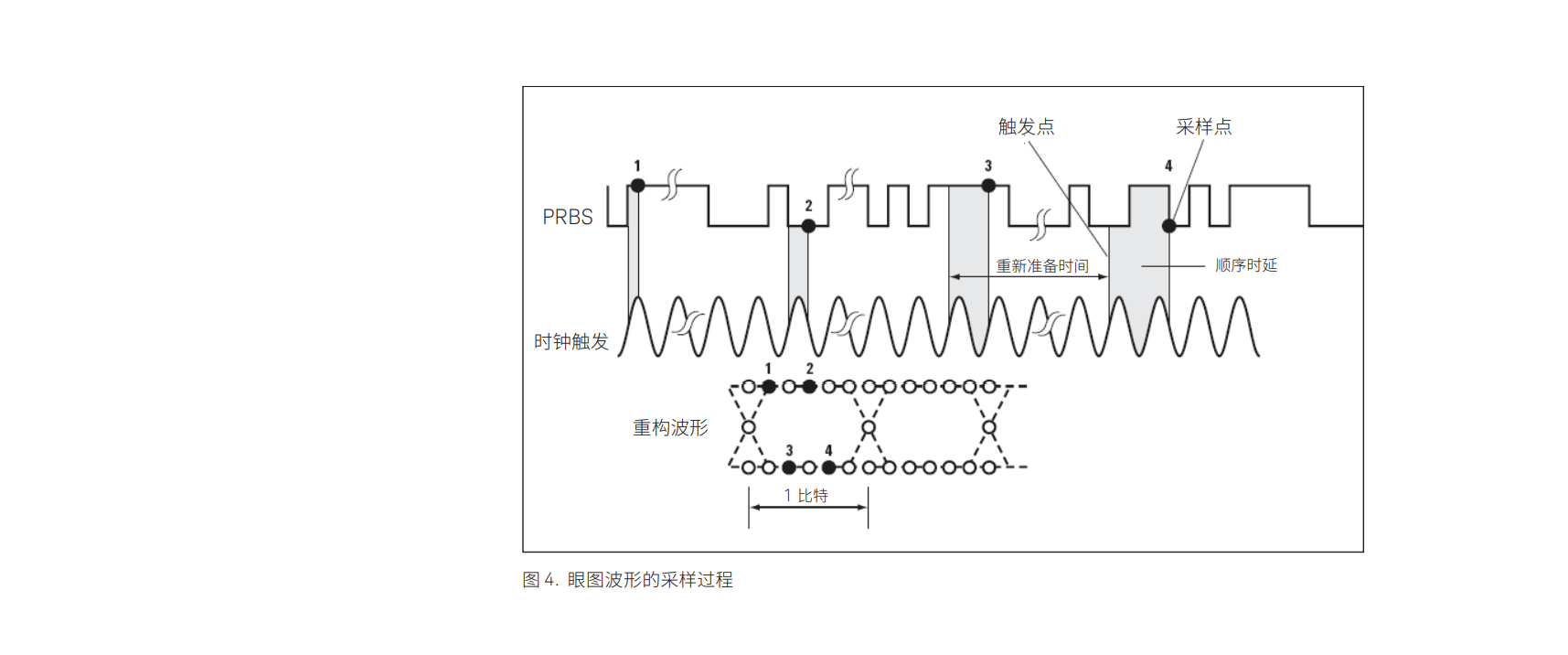
Another signal display mode is the eye diagram. This mode does not require repetitive waveforms and helps determine noise, jitter, distortion, signal strength, and many other measurements. It gives an overall statistical view of system performance because it looks at the superposition of each combination of bits in the bit stream. This mode requires a synchronous clock signal trigger. Whenever a trigger event occurs (allowing the oscilloscope to re-prepare for the trigger), the oscilloscope samples the data and builds all possible combinations of 1s and 0s on the screen. Both full and split clocks can be used for triggering, but if the length of the code pattern is an even multiple of the clock split ratio, the eye diagram will be missing combinations and therefore incomplete. In addition, if the data is used as its own trigger signal, the eye diagram may appear complete, but the oscilloscope will only trigger on the rising edge of the data pattern. To get accurate eye diagram measurements, we should avoid this approach. The trigger process for displaying the eye diagram is shown in Figure 4.
Real-time eye diagram
It is worth noting that you can also view the eye diagram on a newer type of real-time oscilloscope. These "real-time eye diagrams" or "single" eye diagrams are built using a software recovery clock or an external explicit clock provided by the user. Real-time oscilloscopes slice long waveforms captured in a single pass at equal intervals to the recovery clock period, and then overlay the bits to recreate the eye diagram.
Real-Time Oscilloscopes
Equivalent Time Sampling Oscilloscopes for ADCs
A real-time oscilloscope, sometimes called a "single-shot" oscilloscope, captures a complete waveform each time it is triggered. In other words, it captures a large number of data points in a continuous record. To better understand this type of data acquisition, think of it as a very fast analog-to-digital converter (ADC) whose sampling rate determines the sample interval and whose memory depth determines the number of points that will be displayed. In order to capture various waveforms, the sampling rate of the ADC needs to be significantly higher than the frequency of the input waveform. This sampling rate can reach up to 256 GSa/s, which determines the bandwidth that now extends to 110 GHz.
Trigger Real-Time Oscilloscopes
Real-time oscilloscopes can be triggered based on the characteristics of the data itself, usually when the amplitude of the input waveform reaches a certain threshold. At this point, the oscilloscope begins to asynchronously convert the analog waveform to digital data samples at a rate that is independent of the data rate of the input waveform. This conversion rate is called the sample rate and usually comes from the internal clock signal. As shown in Figure 1, the oscilloscope samples the amplitude of the input waveform, saves the sample value to memory, and then proceeds to the next sample. The main task of the trigger is to provide a horizontal time reference point for the input data.
Equivalent Time Sampling Oscilloscope
One sample at a time
An equivalent-time sampling oscilloscope, sometimes referred to as a "sampling oscilloscope," measures only the instantaneous amplitude of the waveform point at the moment of sampling. Unlike a real-time oscilloscope, it only samples the input signal once at each trigger. The oscilloscope adds an hour delay to the next trigger, and then takes the next sample. The number of samples you want to obtain determines the number of waveform periods needed to reproduce the waveform. The measurement bandwidth is determined by the frequency response of the sample head, which can now be extended beyond 80 GHz. There are some very distinct differences in the triggering and subsequent sampling of an equivalent time sampling oscilloscope compared to a real-time oscilloscope.
Sampling Method
Most importantly, the equivalent time sampling oscilloscope requires an explicit trigger to work, and that trigger needs to be synchronized with the input data. The trigger is usually provided by the user, but in some cases a hardware clock recovery module can be used to obtain the trigger signal. The sampling flow is as follows: a trigger event initiates the acquisition of the first sample, and then the oscilloscope is re-prepared for the next trigger event. The next trigger event initiates the second acquisition and adds a precise incremental delay before sampling the second data point. The size of this incremental delay is determined by the time base setting and the number of points sampled. As shown in Figure 2, this process is repeated until the entire waveform is acquired.
Equivalent Time Sampling Oscilloscope (continued)
Triggering the Equivalent Time Sampling Oscilloscope
There are two ways to trigger an equivalent time sampling oscilloscope, resulting in two separate data display formats: bitstream or eye diagram. By viewing individual bits of the signal, the user can understand the code pattern dependencies in the system, but high resolution is not allowed when the number of bits is large. To view the bitstream, the trigger can only fire one pulse during the input pattern period and must be in the same relative position in the bit pattern for each event. The oscilloscope then samples the input signal, adds incremental time delays as the next trigger event occurs, and then samples the bitstream until the entire waveform is captured. If you want to view the bitstream on a time-equivalent oscilloscope, you must have a repeating waveform, otherwise you need to use a real-time oscilloscope. The trigger process to display the bitstream waveform is shown in Figure 3.
Eye Diagram
Creating an eye diagram
Another signal display mode is the eye diagram. This mode does not require repetitive waveforms and helps determine noise, jitter, distortion, signal strength, and many other measurements. It gives an overall statistical view of system performance because it looks at the superposition of each combination of bits in the bit stream. This mode requires a synchronous clock signal trigger. Whenever a trigger event occurs (allowing the oscilloscope to re-prepare for the trigger), the oscilloscope samples the data and builds all possible combinations of 1s and 0s on the screen. Both full and split clocks can be used for triggering, but if the length of the code pattern is an even multiple of the clock split ratio, the eye diagram will be missing combinations and therefore incomplete. In addition, if the data is used as its own trigger signal, the eye diagram may appear complete, but the oscilloscope will only trigger on the rising edge of the data pattern. To get accurate eye diagram measurements, we should avoid this approach. The trigger process for displaying the eye diagram is shown in Figure 4.
Real-time eye diagram
It is worth noting that you can also view the eye diagram on a newer type of real-time oscilloscope. These "real-time eye diagrams" or "single" eye diagrams are built using a software recovery clock or an external explicit clock provided by the user. Real-time oscilloscopes slice long waveforms captured in a single pass at equal intervals to the recovery clock period, and then overlay the bits to recreate the eye diagram.