


34970A Data Collector Getting Started Guide and Basic Explanation


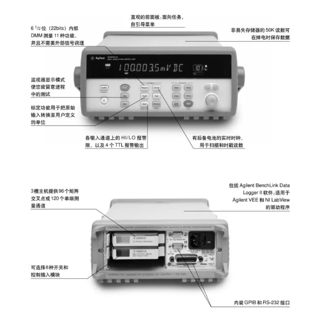
Overview: The 34970A Agilent Data Acquisition/Datalogger Switching Unit consists of a 3-slot mainframe and a built-in 6 1/2-bit digital multimeter. Each channel can be individually configured to measure one of 11 different functions, thus neither increasing cost nor eliminating the need for complex signal conditioning accessories.
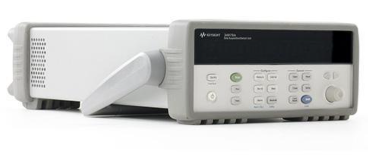
Compact data loggers, full-featured data acquisition systems or low-cost switching units can be built with eight optional insertion modules. Screw connections on the modules eliminate the need for terminal blocks, and a unique relay maintenance feature records the number of closures for each switch, allowing for easy and predictable relay maintenance. 34901A modules have built-in thermocouple references and 20 2-wire channels.
I. 34970A Data Collector Panel Button Functions and Roles
The Agilent 34970A data acquisition application offers versatility, and the 34970A data logger features simplicity of operation, modularity, simple user interface, and flexibility of the data acquisition system for higher performance. (Diagram, panel detail)
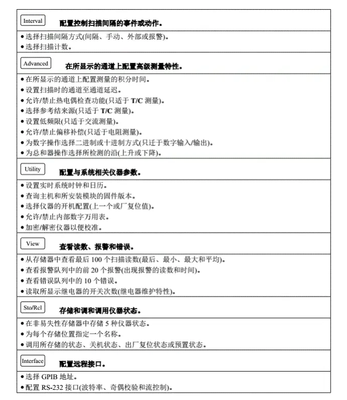
Button function and role (Measure, Mx+B), other can see the illustration
Measure.
Configure measurement parameters on the displayed channel.
● Select the measurement function (DC voltage, resistance, etc.) on the displayed channel;
● Selecting the type of sensor for temperature measurement.
● Select the unit of temperature measurement (°C, F, K);
● Selecting the measurement range or automatic range setting.
● Selecting the resolution of the measurement range.
● Copy and paste the measurement configuration to other channels.
Mx+B Configure calibration parameters for the displayed channel.
● Set the gain ("M") and offset ("B") values for the displayed channel.
● Performing a zero measurement and storing it as an offset.
● Assigning custom markers (RPM, PSI, etc.) to the displayed channel;
II.34970A using BenchLink Data Logger II data collection software
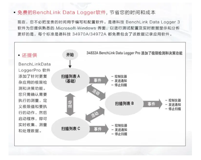
Simplify data collection and analysis with BenchLink Data Logger II software. BenchLink Data Logger II has pc-based data logging capabilities that allow measurement results to be collected and analyzed on a PC with this Windows-based application. Use it to set up tests, collect and archive measurement data, and display and analyze incoming measurement results in real time.
The familiar spreadsheet environment makes it easy to configure and control tests. Rich color charts provide you with a variety of options for analyzing and displaying data - all with a single mouse click. Use line, histogram, bar and scatter plots, results for each channel, and other settings. Of course, BenchLink Data Logger II can also be used to transfer data to other applications for further analysis or report generation.
The basic operation of the button

How to test yourself at power on
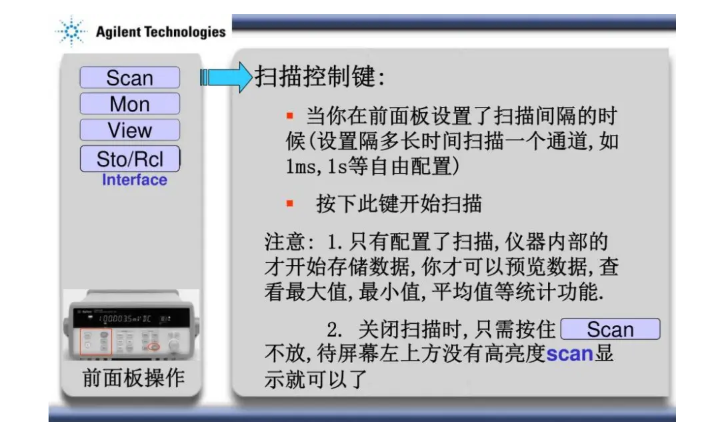
Scan control button
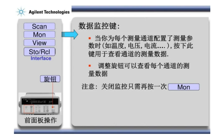
Data monitoring button

Configure remote interface and connect software
Overview: The 34970A Agilent Data Acquisition/Datalogger Switching Unit consists of a 3-slot mainframe and a built-in 6 1/2-bit digital multimeter. Each channel can be individually configured to measure one of 11 different functions, thus neither increasing cost nor eliminating the need for complex signal conditioning accessories.
Compact data loggers, full-featured data acquisition systems or low-cost switching units can be built with eight optional insertion modules. Screw connections on the modules eliminate the need for terminal blocks, and a unique relay maintenance feature records the number of closures for each switch, allowing for easy and predictable relay maintenance. 34901A modules have built-in thermocouple references and 20 2-wire channels.
I. 34970A Data Collector Panel Button Functions and Roles
The Agilent 34970A data acquisition application offers versatility, and the 34970A data logger features simplicity of operation, modularity, simple user interface, and flexibility of the data acquisition system for higher performance. (Diagram, panel detail)
Button function and role (Measure, Mx+B), other can see the illustration
Measure.
Configure measurement parameters on the displayed channel.
● Select the measurement function (DC voltage, resistance, etc.) on the displayed channel;
● Selecting the type of sensor for temperature measurement.
● Select the unit of temperature measurement (°C, F, K);
● Selecting the measurement range or automatic range setting.
● Selecting the resolution of the measurement range.
● Copy and paste the measurement configuration to other channels.
Mx+B Configure calibration parameters for the displayed channel.
● Set the gain ("M") and offset ("B") values for the displayed channel.
● Performing a zero measurement and storing it as an offset.
● Assigning custom markers (RPM, PSI, etc.) to the displayed channel;
II.34970A using BenchLink Data Logger II data collection software
Simplify data collection and analysis with BenchLink Data Logger II software. BenchLink Data Logger II has pc-based data logging capabilities that allow measurement results to be collected and analyzed on a PC with this Windows-based application. Use it to set up tests, collect and archive measurement data, and display and analyze incoming measurement results in real time.
The familiar spreadsheet environment makes it easy to configure and control tests. Rich color charts provide you with a variety of options for analyzing and displaying data - all with a single mouse click. Use line, histogram, bar and scatter plots, results for each channel, and other settings. Of course, BenchLink Data Logger II can also be used to transfer data to other applications for further analysis or report generation.
The basic operation of the button
How to test yourself at power on
Scan control button
Data monitoring button
Configure remote interface and connect software