


How to test OLT with 81250A Agilent?


The 81250A OLT test requires two ONU signals, while the ONU needs an enable signal, so four signals are required. In addition, if it is a GPON system OLT devices, also need a Reset signal, a total of five signals are required.
Other specific configurations are
GEPON OLT: one clock module, 4 Generators and 1 Analyzer module.
GPON OLT: one clock module, 5 Generator, 1 Analyzer module.
OLT sensitivity test setup for GEPON
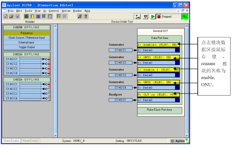
Connect four Generator modules and one Analyzer module to the test area as shown in the figure. (Limited by the demo hardware.
The module E4832A shown in the figure can only cover the test rate up to 622Mb/s For GEPON and GPON devices, it is recommended to use E4861A/E4862A/E4863A2.7Gb/s modules or E4861B/E4862B/E4863B3.35Gb/s modules. This interface is for interface demonstration only.
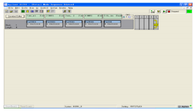
Set the signal rate, Generator output level, and trigger signal as Sequencer, you can refer to the file for the specific steps,Then press Go, DetailEditor to enter the following interface:
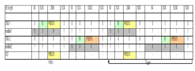
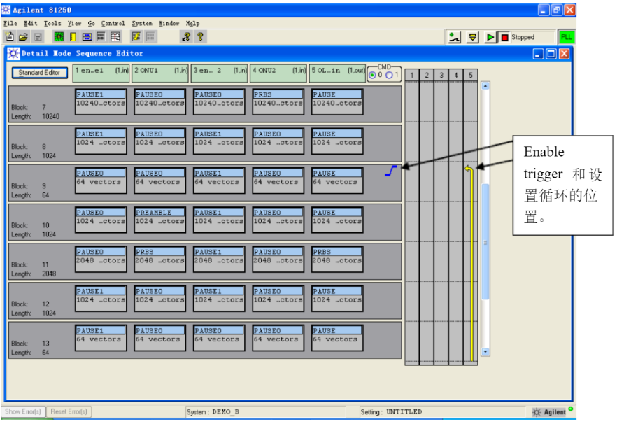
Here we have to set the code type of each sequence according to the requirements of GEPON test. The enable signals are "0" and "1", which are used to turn on and off the laser, and the ONU needs to send the Burst signal, which consists of preamble and PRBS. Since there are two ONU signals and their timing sequence is sequential, it is necessary to stagger the timing of the Burst signals sent by the two ONUs when editing the code pattern.
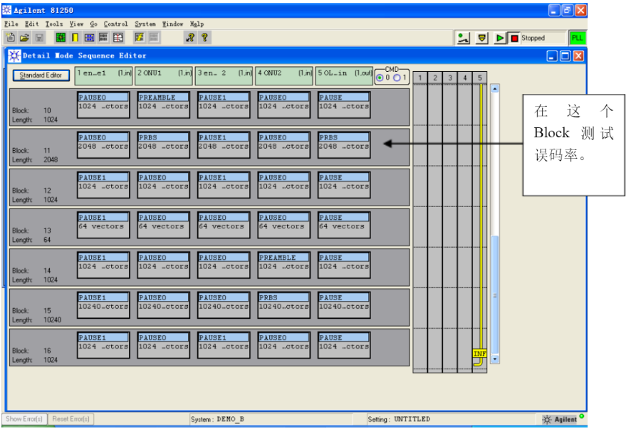
As shown in the chart below, the BitLength of each column in the table represents the length of each Block. Each row represents the signal sent to the ONU and the Generator module of the enable or OLT to send the signal of a different Block, and edit the number in order as shown in the chart (the length of the Block can be changed according to the requirements of the specific device).
The edited yardage interface is shown below.
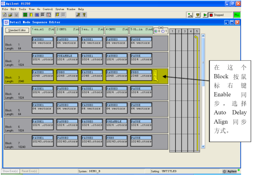
Select enable trigger in the ninth block, and drag the loop arrow to the start of the trigger block.
Before starting the test, you need to set the appropriate delay on the Analyzer manually. You can roughly estimate the delay from Generator, through the cable, ONU, optical patch cable, connected to OLT and then to Analyzer, for example: 2m optical patch cable delay between ONU and OLT: 20ns
ONU delay: 5ns
OLT delay: 5ns
Cable delay: 10ns
Total delay:40ns
The 81250A OLT test requires two ONU signals, while the ONU needs an enable signal, so four signals are required. In addition, if it is a GPON system OLT devices, also need a Reset signal, a total of five signals are required.
Other specific configurations are
GEPON OLT: one clock module, 4 Generators and 1 Analyzer module.
GPON OLT: one clock module, 5 Generator, 1 Analyzer module.
OLT sensitivity test setup for GEPON
Connect four Generator modules and one Analyzer module to the test area as shown in the figure. (Limited by the demo hardware.
The module E4832A shown in the figure can only cover the test rate up to 622Mb/s For GEPON and GPON devices, it is recommended to use E4861A/E4862A/E4863A2.7Gb/s modules or E4861B/E4862B/E4863B3.35Gb/s modules. This interface is for interface demonstration only.
Set the signal rate, Generator output level, and trigger signal as Sequencer, you can refer to the file for the specific steps,Then press Go, DetailEditor to enter the following interface:
Here we have to set the code type of each sequence according to the requirements of GEPON test. The enable signals are "0" and "1", which are used to turn on and off the laser, and the ONU needs to send the Burst signal, which consists of preamble and PRBS. Since there are two ONU signals and their timing sequence is sequential, it is necessary to stagger the timing of the Burst signals sent by the two ONUs when editing the code pattern.
As shown in the chart below, the BitLength of each column in the table represents the length of each Block. Each row represents the signal sent to the ONU and the Generator module of the enable or OLT to send the signal of a different Block, and edit the number in order as shown in the chart (the length of the Block can be changed according to the requirements of the specific device).
The edited yardage interface is shown below.
Select enable trigger in the ninth block, and drag the loop arrow to the start of the trigger block.
Before starting the test, you need to set the appropriate delay on the Analyzer manually. You can roughly estimate the delay from Generator, through the cable, ONU, optical patch cable, connected to OLT and then to Analyzer, for example: 2m optical patch cable delay between ONU and OLT: 20ns
ONU delay: 5ns
OLT delay: 5ns
Cable delay: 10ns
Total delay:40ns