Anritsu MP2110A Testing TEDCQ Method of Operation | BERTWave Bit Error Rate Testing
Operating instructions for the ANRITSU MP2110A test equipment cover detailed steps for connection, setup, calibration, and TDECQ measurements. This document covers the main features of the MP2110A, such as its clock recovery function and test capabilities that can be used for a variety of high-speed communication standards. the MP2110A's procedure for performing TDECQ tests through physical connection, software setup, and calibration. Troubleshooting guides for common test problems, such as setup parameters and potential points of failure to check when test results show anomalies. and a supplementary tool, TDECQ Assistant, which helps users simplify the test setup and measurement process. This document provides users with a complete set of operating procedures and troubleshooting methods to ensure that they can effectively use the MP2110A to perform high-quality high-speed communication standard tests.
一、MP2110A Oscilloscope Front Panel and Connection Schematics
Wiring schematic 1/3: Using external triggering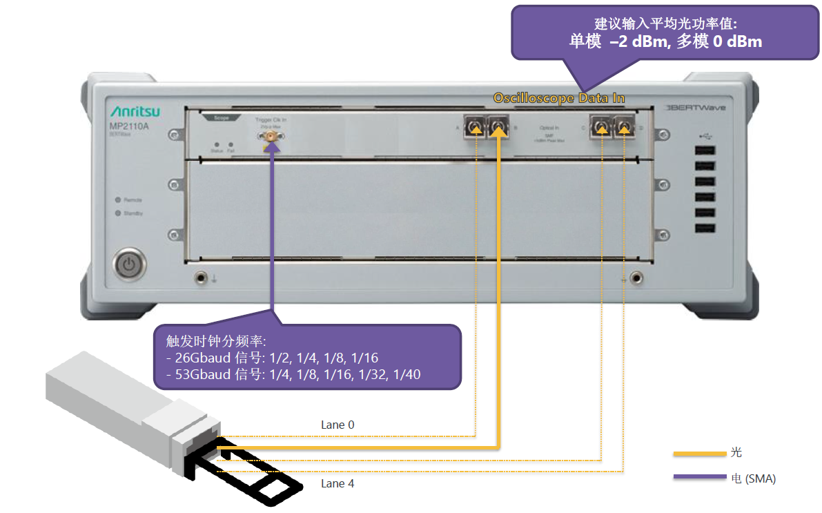
Wiring Schematic 2/3: Using Option-054 26G CRU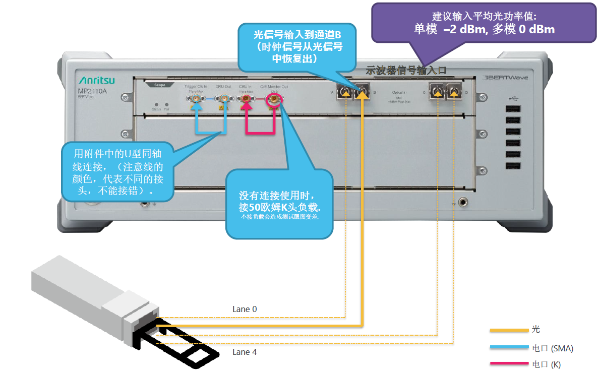
Connection schematic circuit diagram 3/3: Using the Option-055 26G/53G CRU

二、MP2110A setup initialization operation, CRU operation flow, calibration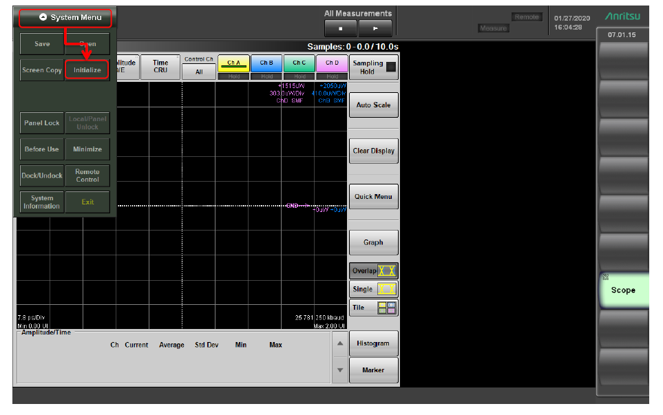
2.1 Setting Initialization Operation
2.2 CRU Operation Flow
2.1 Selecting Rate Tracking Mode: CRU
2.2 Select operation mode: Recovery
2.3 Select clock recovery rate: 26.5625G or 53.125G.
2.4 Check clock recovery lock status

2.3 Calibration
Oscilloscopes must be calibrated after a period of time. Failure to calibrate the oscilloscope will affect the test program, especially the amplitude.

三、TDECQ Measurement Procedure
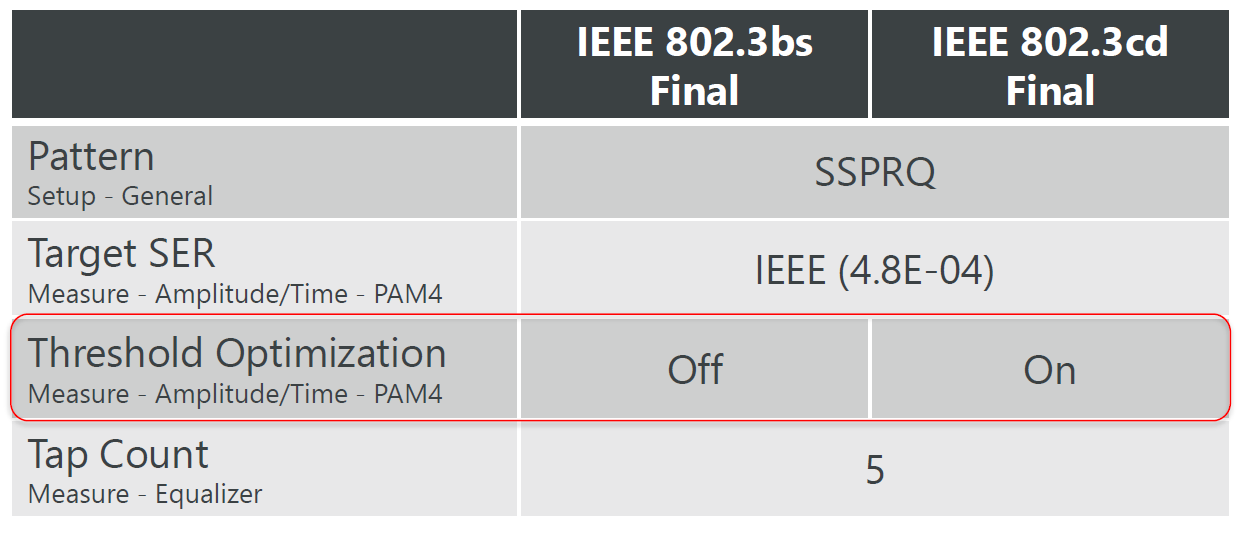
TDECQ Measurement Procedure with MP2110A. After connecting the PAM4 and trigger signals, follow this procedure to perform the test, and the TDECQ measurement procedure refers to the IEEE 802.3cd Final standard.
(1) Select Setup and set Signal Type to PAM4.
Set Sampling Mode to Coherent Eye.
Set Test Pattern (pattern length) from the following options:
PRBS7: 127 symbols
PRBS9: 511 symbols
PRBS13: 8191 symbols (recommended)
PRBS15: 32767 symbols (recommended)
SSPRQ: 65535 symbols (recommended)
*Variable length cannot be selected for TDECQ testing (using digital reference filter and TDECQ equalizer).
(2) Set Accumulation Type to Limited and set Limit Type to Pattern (to capture the number of patterns).

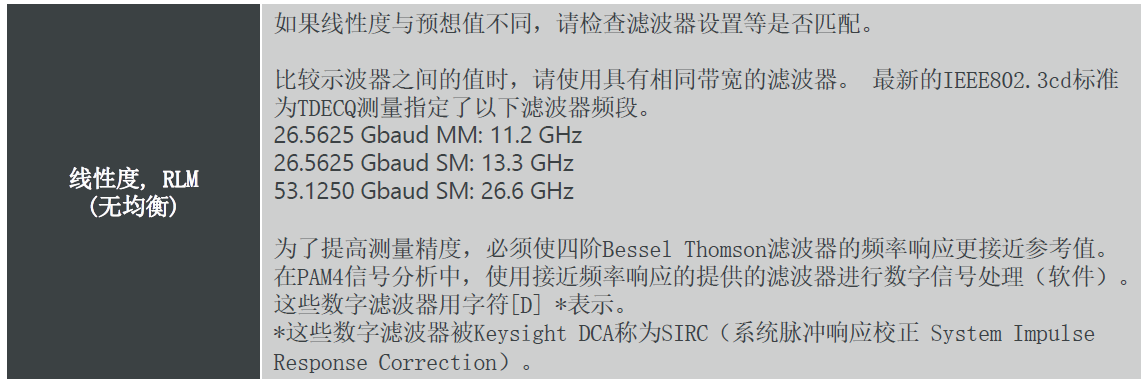
(3)Select the Amplitude/OE and OE tabs. Set the Input Connector (Wavelength) and select the Filter according to the table below.*Filters with [D] in their names are digital filters. Digital filters can be selected only when Coherent Eye and Pattern are set.
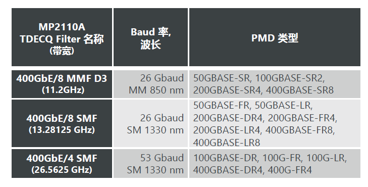
Set the reference filter method.
*Filters with [D] in the filter name are digital filters. Digital filters can be selected only when Coherent Eye and Pattern are set.
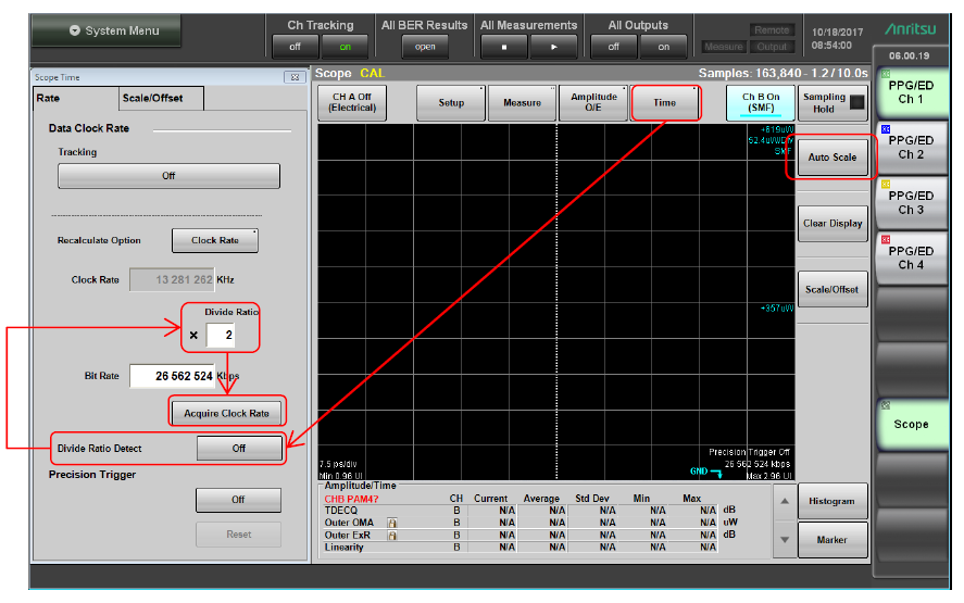
When CRU is not used, set the trigger input as follows.(4) Select Time.

How to add a measurement item?
(6) Select Measure. Select Item Type: NRZ.
Select the test item: Average Power.
Select Item Type: PAM4.
Select the test item: TDECQ Outer OMA Outer ExR Linearity Ceq, etc.

Measure by repeating the following steps.

IEEE Standard TDECQ Settings


五、Test Problem Troubleshooting
If the PAM4 eye chart and TDECQ measurements are displayed incorrectly, see the following.
1. Check the following Setup settings and reset them.
Signal Type: PAM4
Sampling Mode: Coherent Eye
Test Pattern: *Variable Pattern length cannot be selected when testing TDECQ.
2. Check the Trigger Clock Divide Ratio: - 26Gbaud Signal: 1/2, 1/4, 1/8, 1/16 - 53Gbaud Signal: 1/4, 1/8, 1/16, 1/32, 1/40 (when Coherent Eye Mode Pulse Mode is selected.)
3. Click Setup - Utilities - Calibration one at a time. While calibrating, turn off the Data and Trigger inputs. Please refer to the “Calibration” section in the documentation.
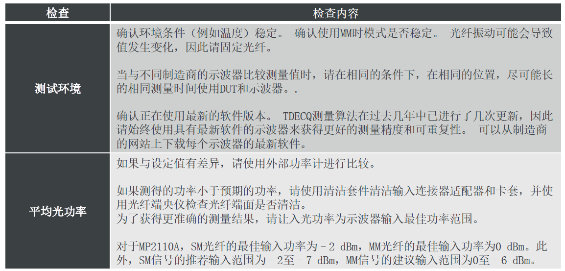
4. Check the average optical power of the input signal. SMF: -2 dBm MMF: 0 dBm

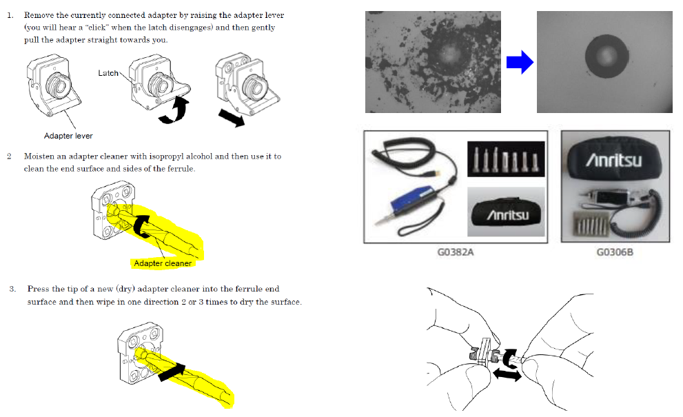
5. Use a fiber optic end-face meter to check the cleanliness of fiber optics and fiber optic connectors/adapters
Checking the measured values

Operating instructions for the ANRITSU MP2110A test equipment cover detailed steps for connection, setup, calibration, and TDECQ measurements. This document covers the main features of the MP2110A, such as its clock recovery function and test capabilities that can be used for a variety of high-speed communication standards. the MP2110A's procedure for performing TDECQ tests through physical connection, software setup, and calibration. Troubleshooting guides for common test problems, such as setup parameters and potential points of failure to check when test results show anomalies. and a supplementary tool, TDECQ Assistant, which helps users simplify the test setup and measurement process. This document provides users with a complete set of operating procedures and troubleshooting methods to ensure that they can effectively use the MP2110A to perform high-quality high-speed communication standard tests.
一、MP2110A Oscilloscope Front Panel and Connection Schematics
Wiring schematic 1/3: Using external triggering
Wiring Schematic 2/3: Using Option-054 26G CRU
Connection schematic circuit diagram 3/3: Using the Option-055 26G/53G CRU

二、MP2110A setup initialization operation, CRU operation flow, calibration
2.1 Setting Initialization Operation
2.2 CRU Operation Flow
2.1 Selecting Rate Tracking Mode: CRU
2.2 Select operation mode: Recovery
2.3 Select clock recovery rate: 26.5625G or 53.125G.
2.4 Check clock recovery lock status

2.3 Calibration
Oscilloscopes must be calibrated after a period of time. Failure to calibrate the oscilloscope will affect the test program, especially the amplitude.

三、TDECQ Measurement Procedure
TDECQ Measurement Procedure with MP2110A. After connecting the PAM4 and trigger signals, follow this procedure to perform the test, and the TDECQ measurement procedure refers to the IEEE 802.3cd Final standard.
(1) Select Setup and set Signal Type to PAM4.
Set Sampling Mode to Coherent Eye.
Set Test Pattern (pattern length) from the following options:
PRBS7: 127 symbols
PRBS9: 511 symbols
PRBS13: 8191 symbols (recommended)
PRBS15: 32767 symbols (recommended)
SSPRQ: 65535 symbols (recommended)
*Variable length cannot be selected for TDECQ testing (using digital reference filter and TDECQ equalizer).
(2) Set Accumulation Type to Limited and set Limit Type to Pattern (to capture the number of patterns).

(3)Select the Amplitude/OE and OE tabs. Set the Input Connector (Wavelength) and select the Filter according to the table below.*Filters with [D] in their names are digital filters. Digital filters can be selected only when Coherent Eye and Pattern are set.

Set the reference filter method.
*Filters with [D] in the filter name are digital filters. Digital filters can be selected only when Coherent Eye and Pattern are set.

When CRU is not used, set the trigger input as follows.(4) Select Time.

How to add a measurement item?
(6) Select Measure. Select Item Type: NRZ.
Select the test item: Average Power.
Select Item Type: PAM4.
Select the test item: TDECQ Outer OMA Outer ExR Linearity Ceq, etc.

Measure by repeating the following steps.

IEEE Standard TDECQ Settings


五、Test Problem Troubleshooting
If the PAM4 eye chart and TDECQ measurements are displayed incorrectly, see the following.
1. Check the following Setup settings and reset them.
Signal Type: PAM4
Sampling Mode: Coherent Eye
Test Pattern: *Variable Pattern length cannot be selected when testing TDECQ.
2. Check the Trigger Clock Divide Ratio: - 26Gbaud Signal: 1/2, 1/4, 1/8, 1/16 - 53Gbaud Signal: 1/4, 1/8, 1/16, 1/32, 1/40 (when Coherent Eye Mode Pulse Mode is selected.)
3. Click Setup - Utilities - Calibration one at a time. While calibrating, turn off the Data and Trigger inputs. Please refer to the “Calibration” section in the documentation.
4. Check the average optical power of the input signal. SMF: -2 dBm MMF: 0 dBm

5. Use a fiber optic end-face meter to check the cleanliness of fiber optics and fiber optic connectors/adapters

Checking the measured values


