


KEYSIGHT E5071C Calibration Operation Introduction | Network Analyzer ENA


Introduction of Network Analyzer E5071C
The working principle of network analyzer:
By capturing the reflected wave of the device to be measured, the network score can measure the impedance value, VSWR, return loss and other parameters of the device to be measured at each frequency point, and reflect them on the screen of the network score.
E5071C Front Panel Introduction:
Overview:
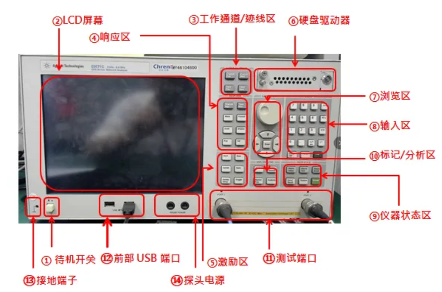
Details:
① Standby switch: switch between power-on and standby status.
② LCD screen: Display trace, scale, setting, function keys and test information.
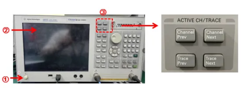
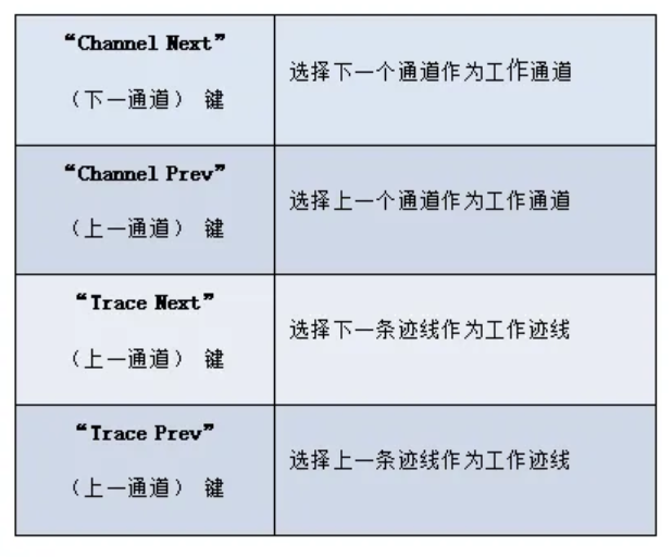
③ Working channel / trace area:
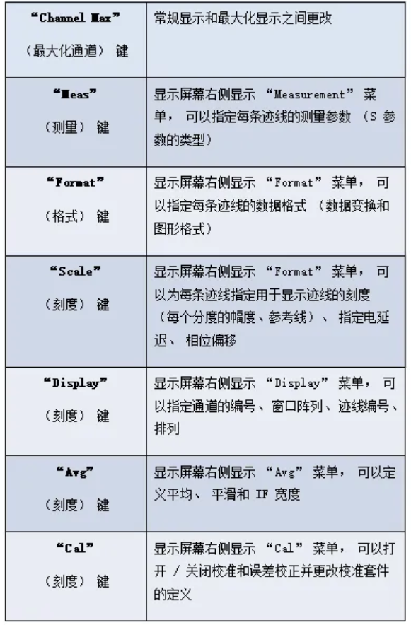
④ Response area: Setting up a set of keys for response measurement
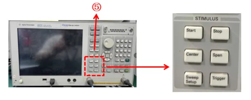
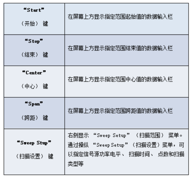
⑤ Excitation area: define the excitation value (source and trigger) A set of keys
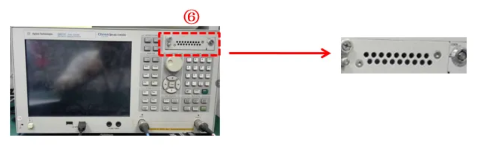
⑥ Hard disk drive: access to a removable hard disk
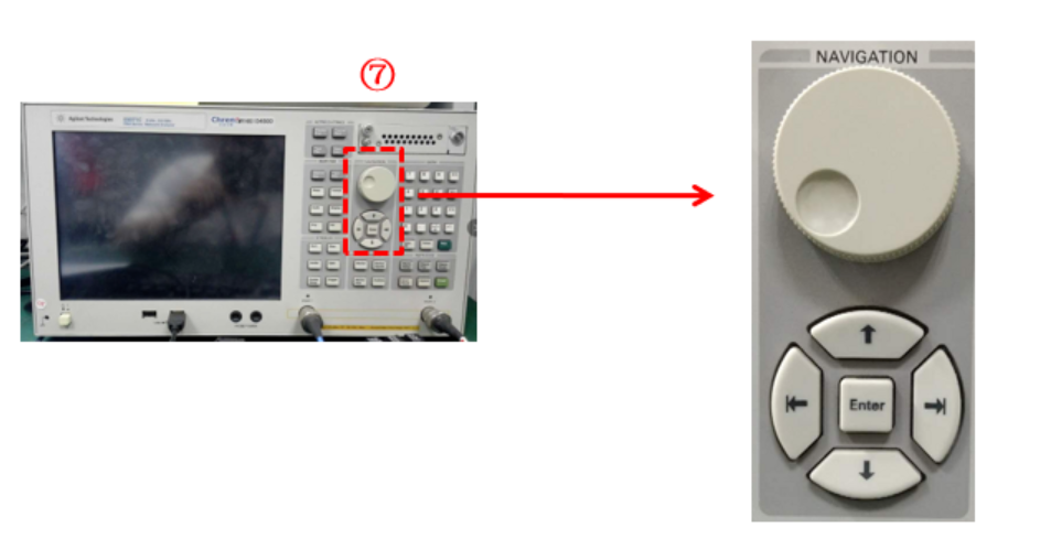
⑦ Browse Area: The buttons and knobs in the Browse Area are used to navigate through selected areas of function menus, tables, and dialog boxes, and to change values in the data entry area by increasing or decreasing them.
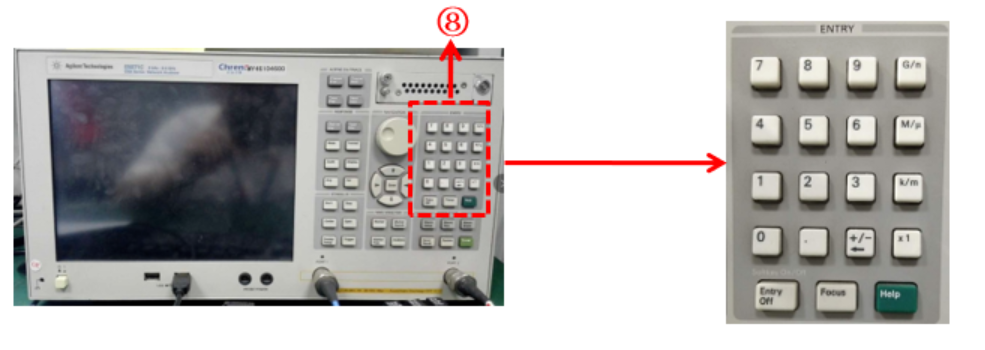
⑧ Input area:
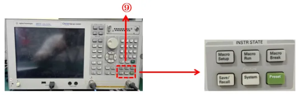
⑨ Instrument status area:
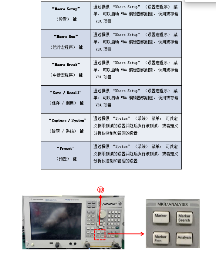
⑩ Marker/analysis area: Analyze measurement results by using markers, fixture simulators, etc.
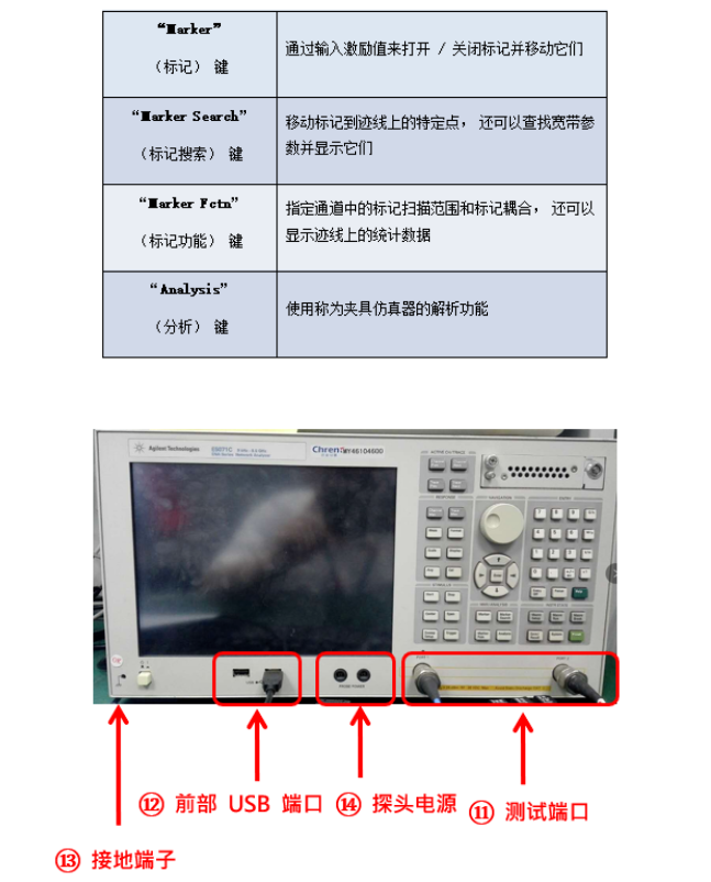
⑪ Test port: The port to which the DUT (Device Under Test) is connected. The number of ports depends on the option.
⑫ Front USB port: Connects to the Ecal module, USB, multi-port test set, or printer.
⑬ Ground terminal: The ground terminal of the E5071C, connected to the chassis of the device.
⑭ Probe Power: Port that provides power to the external probe.
Introduction of Network Analyzer E5071C
The working principle of network analyzer:
By capturing the reflected wave of the device to be measured, the network score can measure the impedance value, VSWR, return loss and other parameters of the device to be measured at each frequency point, and reflect them on the screen of the network score.
E5071C Front Panel Introduction:
Overview:
Details:
① Standby switch: switch between power-on and standby status.
② LCD screen: Display trace, scale, setting, function keys and test information.
③ Working channel / trace area:
④ Response area: Setting up a set of keys for response measurement
⑤ Excitation area: define the excitation value (source and trigger) A set of keys
⑥ Hard disk drive: access to a removable hard disk
⑦ Browse Area: The buttons and knobs in the Browse Area are used to navigate through selected areas of function menus, tables, and dialog boxes, and to change values in the data entry area by increasing or decreasing them.
⑧ Input area:
⑨ Instrument status area:
⑩ Marker/analysis area: Analyze measurement results by using markers, fixture simulators, etc.
⑪ Test port: The port to which the DUT (Device Under Test) is connected. The number of ports depends on the option.
⑫ Front USB port: Connects to the Ecal module, USB, multi-port test set, or printer.
⑬ Ground terminal: The ground terminal of the E5071C, connected to the chassis of the device.
⑭ Probe Power: Port that provides power to the external probe.