Keysight N1092A Series What factors in eye chart testing affect the accuracy of test results?
When performing the Keysight N1092A eye chart test, a variety of factors may affect the accuracy of the test results. The following are some of the key factors:
Bias Current: Improper setting of the bias current may result in the bottom of the waveform being too low, affecting the clarity of the eye chart. Increasing the bias current appropriately can move the bottom of the waveform upward, resulting in a clearer eye diagram.
Rising Edge Speed: If the rising edge speed is too fast, it may lead to overshoot phenomenon, i.e., the rising edge of the waveform exceeds 1 level. This can be solved by inserting a low-pass filter RC circuit or adjusting the value of the series damping resistor RD.
Overdamping: Overdamping can cause the rising or falling edge of the waveform to not reach the high or low level position. Adjusting the value of the series damping resistor RD reduces the overdamping and matches the output impedance to reduce the attenuation.
Impedance discontinuities: Impedance discontinuities in the circuit may lead to vibration phenomena. Impedance discontinuities should be eliminated as much as possible and component pin lengths should be reduced to minimise parasitic inductance.
Reflections: Reflections may occur at the receiving end due to transmission line impedance discontinuities. The distance between the laser driver and the laser diode should be minimised and correct impedance control considered.
NRZ Data Continuity: For reverse non-return-to-zero (NRZ) data, too many consecutive bits may result in double lines or jittery graphics. This can be resolved by increasing the series damping resistor RD or VCC, or reducing the modulation current IMOD.
Symmetry: If the eye diagram is not symmetrical and the rise and fall times are not equal, this may be due to different charge and discharge paths used for the rising and falling edges. A symmetrical laser tube should be used or the series damping resistor RD should be adjusted until the rise and fall times are equal.
Oscillations and Overshoots: If the eye diagram shows oscillations and significant overshoots, this may be due to the bias current IBIAS being too small. Increasing the bias current will gradually reduce the overshoot.
Terminal termination impedance mismatch: PCB process, design deviation and other factors may lead to terminal termination impedance and transmission line characteristic impedance mismatch, thus generating reflections. Attention should be paid to impedance matching during design to avoid reflection affecting the eye diagram.
Transmitter signal pre-processing: improper signal pre-processing at the transmitter, such as pre-emphasis or de-emphasis processing, will also affect the quality of the eye diagram. It should be handled carefully so as not to introduce additional high-frequency noise.
Improper receiver equalisation: Improper receiver equalisation may lead to distortion of the eye diagram. Equalisation should be optimised to reduce inter-code crosstalk and improve the transmission performance of the system.
Channel crosstalk: Serious channel crosstalk may lead to eye diagram distortion. Measures should be taken to reduce inter-channel interactions to maintain the clarity of the eye diagram.

Factors that contribute to the accuracy of Keysight N1092A eye diagram test results include bias current, rising edge speed, overdamping, impedance discontinuities, reflections, NRZ data continuity, symmetry, oscillations and overshoots, termination termination impedance mismatches, improper signal preprocessing on the transmitter side and equalisation processing on the receiver side, and channel crosstalk. When performing the test, these factors should be considered comprehensively and measures should be taken to optimise the test conditions to ensure the accuracy of the results.
N1092A Eye Diagram Test Procedure (Reference)
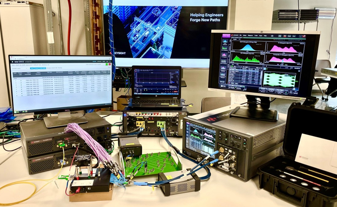
The N1092A is a DE DCA-M sampling oscilloscope that supports a variety of functions such as eye diagram testing and optical module/optical cat testing. The following are the basic steps for eye diagram testing with the N1092A:
Preparation:
Make sure the N1092A unit is properly installed and connected to the power supply.
Select appropriate test accessories such as fibre optic connectors, fibre optic cables, optical probes, etc. as required.
If required, install the FlexDCA software, which is necessary for controlling and analysing the N1092A.
Connect the device:
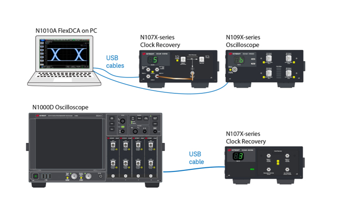
Connect the PC directly to the N1092A using a USB cable.
Connect the 86100D host computer directly to the N1092A via a USB cable (the 86100D can then be controlled via GPIB or LAN).
In an automated test system environment, the main test system PC is connected to a low-cost computer via LAN and the FlexDCA interface resides on a second PC. The second PC is then connected to the N1092A via USB.
Configure test parameters:
Open the FlexDCA software and configure the software as needed to connect to the N1092A.
Select the correct serial port (COM port) for the USB to serial converter interface as well as set the appropriate communication parameters.
Start the test:
Launch the FlexDCA software and attempt to establish a connection to the N1092A.
Once the connection is successful, you can perform various operations of the eye chart test through the software interface, such as setting test parameters, starting the test, and viewing and analysing the test results.
Result Analysis:
Based on the test results, the performance of the optical communication system is evaluated, such as the degree of opening and closing of the eye diagram, jitter, and so on.
If needed, the system parameters can be adjusted and the test can be repeated to optimise the performance.
The above steps are based on the information compiled in the search results, the specific operation may vary according to the actual network environment and equipment configuration.

When performing the Keysight N1092A eye chart test, a variety of factors may affect the accuracy of the test results. The following are some of the key factors:
Bias Current: Improper setting of the bias current may result in the bottom of the waveform being too low, affecting the clarity of the eye chart. Increasing the bias current appropriately can move the bottom of the waveform upward, resulting in a clearer eye diagram.
Rising Edge Speed: If the rising edge speed is too fast, it may lead to overshoot phenomenon, i.e., the rising edge of the waveform exceeds 1 level. This can be solved by inserting a low-pass filter RC circuit or adjusting the value of the series damping resistor RD.
Overdamping: Overdamping can cause the rising or falling edge of the waveform to not reach the high or low level position. Adjusting the value of the series damping resistor RD reduces the overdamping and matches the output impedance to reduce the attenuation.
Impedance discontinuities: Impedance discontinuities in the circuit may lead to vibration phenomena. Impedance discontinuities should be eliminated as much as possible and component pin lengths should be reduced to minimise parasitic inductance.
Reflections: Reflections may occur at the receiving end due to transmission line impedance discontinuities. The distance between the laser driver and the laser diode should be minimised and correct impedance control considered.
NRZ Data Continuity: For reverse non-return-to-zero (NRZ) data, too many consecutive bits may result in double lines or jittery graphics. This can be resolved by increasing the series damping resistor RD or VCC, or reducing the modulation current IMOD.
Symmetry: If the eye diagram is not symmetrical and the rise and fall times are not equal, this may be due to different charge and discharge paths used for the rising and falling edges. A symmetrical laser tube should be used or the series damping resistor RD should be adjusted until the rise and fall times are equal.
Oscillations and Overshoots: If the eye diagram shows oscillations and significant overshoots, this may be due to the bias current IBIAS being too small. Increasing the bias current will gradually reduce the overshoot.
Terminal termination impedance mismatch: PCB process, design deviation and other factors may lead to terminal termination impedance and transmission line characteristic impedance mismatch, thus generating reflections. Attention should be paid to impedance matching during design to avoid reflection affecting the eye diagram.
Transmitter signal pre-processing: improper signal pre-processing at the transmitter, such as pre-emphasis or de-emphasis processing, will also affect the quality of the eye diagram. It should be handled carefully so as not to introduce additional high-frequency noise.
Improper receiver equalisation: Improper receiver equalisation may lead to distortion of the eye diagram. Equalisation should be optimised to reduce inter-code crosstalk and improve the transmission performance of the system.
Channel crosstalk: Serious channel crosstalk may lead to eye diagram distortion. Measures should be taken to reduce inter-channel interactions to maintain the clarity of the eye diagram.

Factors that contribute to the accuracy of Keysight N1092A eye diagram test results include bias current, rising edge speed, overdamping, impedance discontinuities, reflections, NRZ data continuity, symmetry, oscillations and overshoots, termination termination impedance mismatches, improper signal preprocessing on the transmitter side and equalisation processing on the receiver side, and channel crosstalk. When performing the test, these factors should be considered comprehensively and measures should be taken to optimise the test conditions to ensure the accuracy of the results.
N1092A Eye Diagram Test Procedure (Reference)
The N1092A is a DE DCA-M sampling oscilloscope that supports a variety of functions such as eye diagram testing and optical module/optical cat testing. The following are the basic steps for eye diagram testing with the N1092A:
Preparation:
Make sure the N1092A unit is properly installed and connected to the power supply.
Select appropriate test accessories such as fibre optic connectors, fibre optic cables, optical probes, etc. as required.
If required, install the FlexDCA software, which is necessary for controlling and analysing the N1092A.
Connect the device:
Connect the PC directly to the N1092A using a USB cable.
Connect the 86100D host computer directly to the N1092A via a USB cable (the 86100D can then be controlled via GPIB or LAN).
In an automated test system environment, the main test system PC is connected to a low-cost computer via LAN and the FlexDCA interface resides on a second PC. The second PC is then connected to the N1092A via USB.
Configure test parameters:
Open the FlexDCA software and configure the software as needed to connect to the N1092A.
Select the correct serial port (COM port) for the USB to serial converter interface as well as set the appropriate communication parameters.
Start the test:
Launch the FlexDCA software and attempt to establish a connection to the N1092A.
Once the connection is successful, you can perform various operations of the eye chart test through the software interface, such as setting test parameters, starting the test, and viewing and analysing the test results.
Result Analysis:
Based on the test results, the performance of the optical communication system is evaluated, such as the degree of opening and closing of the eye diagram, jitter, and so on.
If needed, the system parameters can be adjusted and the test can be repeated to optimise the performance.
The above steps are based on the information compiled in the search results, the specific operation may vary according to the actual network environment and equipment configuration.


