


10G Optical Module Eye Diagram Testing in a Nutshell


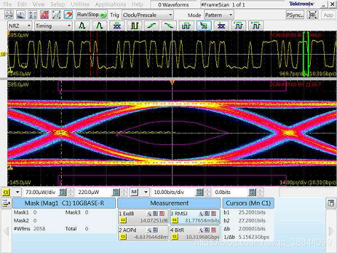
10G optical module eye diagram test is an important means to evaluate the performance of optical modules, which is a method to obtain the performance parameters of optical modules by monitoring and analysing the optical signals in real time. During the testing process, the optical signal is converted into an electrical signal and displayed through the waveform of an oscilloscope. By analysing the waveform, various parameters of the eye diagram, such as eye height, eye width, extinction ratio, etc., can be obtained to evaluate the performance of the optical module.
What equipment is commonly used in 10G optical module eye diagram testing?
High-speed digital oscilloscope: It is used to capture the signal waveform sent by the optical module and display it as an eye diagram graph. The sampling rate and bandwidth of the oscilloscope should at least match the operating rate of the optical module.
Waveform generator: Used to generate specific test signals in order to simulate the working environment of the optical module in the actual application.
Optical Module: As the object to be tested, its performance will be evaluated by eye diagram test.
Optical Attenuator: Used to adjust the input optical signal strength to fit the dynamic range of the oscilloscope.
Optical Fibre: Used to connect the optical module and other test equipment to transmit the optical signal.
Clock Source: Provides synchronisation signals to ensure time consistency between test equipment.
Synchronisation Receiver: Used to receive and decode signals from the optical module so that the oscilloscope can accurately capture the signal waveform.
Eye Diagram Analysis Software: Used to process the data captured by the oscilloscope and generate eye diagram graphs to analyse the performance parameters of the optical module, such as noise and jitter.
The above equipment together constitute a complete 10G optical module eye diagram test system, through which the performance of the optical module can be comprehensively assessed to ensure its stability and reliability in high-speed data transmission. Before conducting the test, it should be ensured that all equipment has been properly configured and operated according to the test protocol.