


Keysight n1092a Oscilloscope, How to Eye Diagram BERT Test, Optical Module/Optical Cat Universal


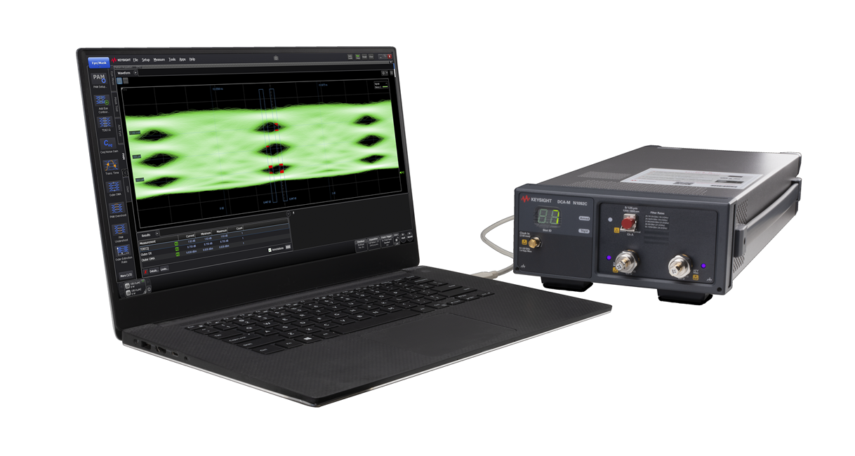
The test method for the N1092A consists of two main ways. The first is to use a USB cable to connect directly to the N1092A/B/C/D/E's PC for control. These two methods provide flexible connection options to suit different testing needs and environments.
What are the exact steps for connecting the N1092A/B/C/D/E's USB to a PC?
The specific steps for connecting the N1092A/B/C/D/E's USB to a PC are as follows:
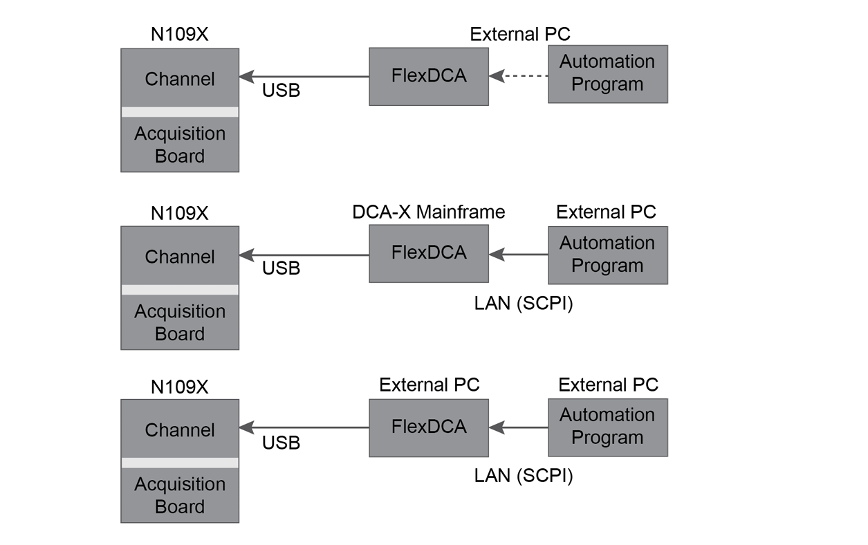
Use a USB cable to connect a PC directly to the N1092A/B/C/D/E. This is one way to control the N109X system.
The connection to the N1092A/B/C/D/E can be achieved by connecting the TX and RX wires on the UART interface to the PC using a USB to RS232 board.
It is also possible to connect the 86100D or N1000A host computer to the N1092A/B/C/D/E using a USB cable. the host computer can be controlled via GPIB or other means, and then the host computer can be controlled via GPIB or LAN.
There are three main methods of connecting the N1092A/B/C/D/E to a PC: directly using a USB cable, using a USB to RS232 board connection, and through the 86100D or N1000A host computer. These methods provide flexible control options to suit different application scenarios and needs.
How to connect the PC of the main test system to a low-cost modern PC using LAN and how to control the N1092A/B/C/D/E from a second PC via USB?
To connect the PC of the main test system to a low-cost modern PC and to control the N1092A/B/C/D/E from a second PC via USB, the following steps can be followed:
Connection method: firstly, the connection method needs to be determined. the N1092A/B/C/D/E series devices can be controlled from a PC via the USB interface. This means that if it is desired to connect two PCs via LAN (Local Area Network), it may be necessary to use a device or software that supports LAN connection for this purpose.
Using flexdca Remote Interface Software: According to the evidence, flexdca is a software that can remotely control the n1090a series, and it supports connecting a PC to the oscilloscope via a LAN, GPIB or USB interface. Although the n1090a series is mentioned here, considering that the N1092A/B/C/D/E series also supports control via USB, it can be surmised that the flexdca software is also applicable to the N1092A/B/C/D/E series, especially in terms of control via USB.
Setting up the network environment: In order to connect two PCs via LAN, it is necessary to ensure that they are on the same LAN. This usually involves configuring network settings such as IP addresses, subnet masks and default gateways to ensure that the two PCs can communicate with each other.
Install and configure flexdca software: Install the flexdca software on the second PC and configure the software as required to connect to the N1092A/B/C/D/E Series devices. This may include selecting the correct serial port (COM port) for the USB to serial converter interface and setting the appropriate communication parameters.
Start and Test Connection: After completing the above configuration, start the flexdca software and attempt to establish a connection to the N1092A/B/C/D/E series device. If everything is set up correctly, it should be possible to successfully control the N1092A/B/C/D/E series device from a second PC via the USB interface.
By following the above steps, it is possible to connect the PC of the main test system to a low-cost modern PC via LAN and to control the N1092A/B/C/D/E from a second PC via USB. Note that the exact operation may vary depending on the actual network environment and device configuration.
What types of tests and functions are supported by the N1092A/B/C/D/E?
The main tests and functions supported by the N1092A/B/C/D/E include:
Optical Channel Bandwidth: These units provide electrical channel bandwidths of 40 GHz (Option 40A) and 50 GHz, and optical channel bandwidths of 28/45 GHz (two optical channels). In particular, the N1092A option has an optical channel bandwidth of 28 GHz.
Input types: FC/PC and 2.4 mm input type 2629 are supported.
High Sensitivity: The noise floor is only 5 μW (optical) and 310/600 µV (electrical), which demonstrates its high sensitivity.
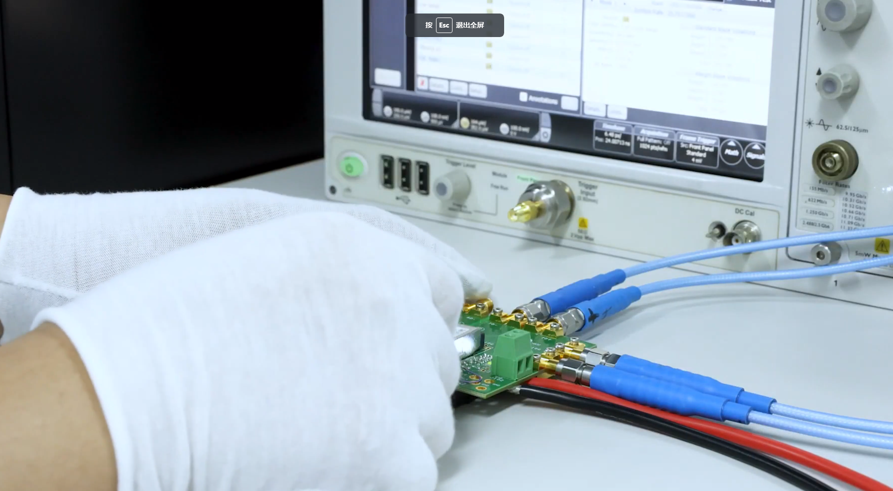
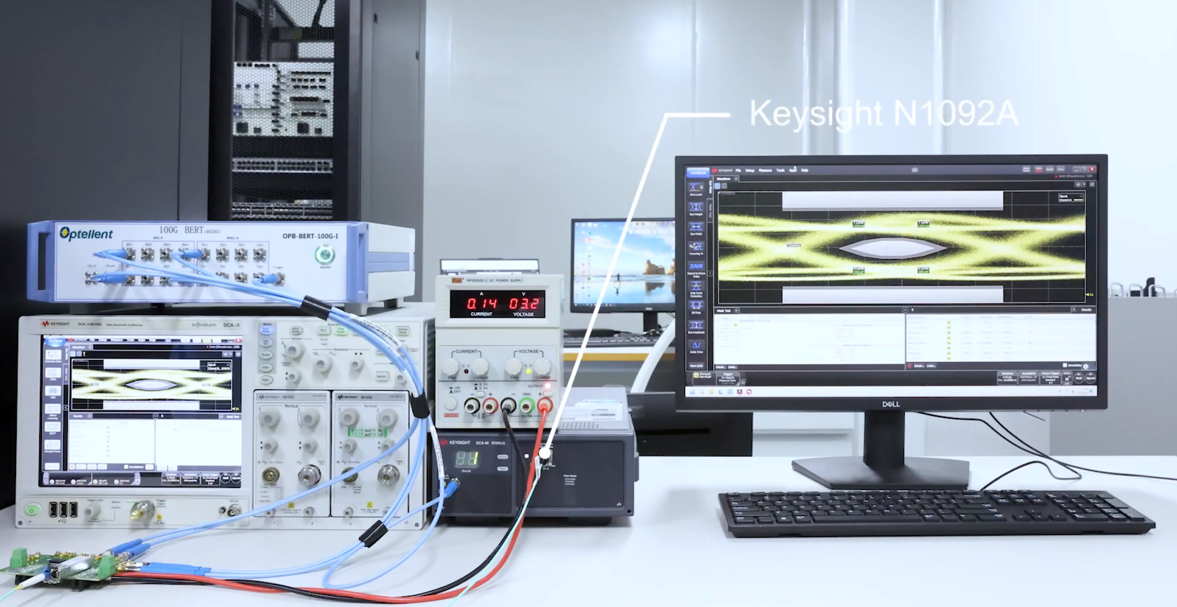
Optical Module/Optical Cat Test: The N1092 series is mentioned as an eye diagram BERT test solution for optical modules/optical cats, including PAM4 & NRZ formats.
Optical Waveform Analysis: Provides highly accurate and cost-effective optical waveform analysis solutions.
Sampling Oscilloscope Functions: As DCA-M Sampling Oscilloscopes, they combine high-performance elements, including the N1000 and 86100 oscilloscope main frame acquisition systems as well as optoelectronic signal channel hardware for the 861XX and N104X plug-in modules.
User guides and accessories: Detailed user guides and accessories are provided to help users better understand and use these devices.
The tests and functions supported by the N1092A/B/C/D/E cover a wide range of needs from optical channel bandwidth, input type, and high sensitivity to specific optical module/optical cat test solutions, as well as optical waveform analysis.
What are the common problems and their solutions when testing with N1092A/B/C/D/E?
I'm sorry, but your search and my search did not include specific information about common problems and their solutions when testing with the N1092A/B/C/D/E. Therefore, based on the available evidence, I am unable to answer your question directly. If you have additional material or information that I have searched for, please provide it so that I can more accurately answer your question.
For N1092A/B/C/D/E, what specialised software or tools are available to assist in its testing?
For the N1092A/B/C/D/E, specialised software or tools that can be used include the FlexOTO Optical Test Optimisation software and solution from YesTech. In addition, Proteus simulation software can also assist in teaching microcontrollers and although it is primarily used for teaching purposes, it is also suitable for test work related to the N1092A/B/C/D/E. These tools and software can provide the necessary support to ensure the accuracy and efficiency of the N1092A/B/C/D/E when performing data acquisition and analysis with an optoelectronic signal sampling oscilloscope.
The test method for the N1092A consists of two main ways. The first is to use a USB cable to connect directly to the N1092A/B/C/D/E's PC for control. These two methods provide flexible connection options to suit different testing needs and environments.
What are the exact steps for connecting the N1092A/B/C/D/E's USB to a PC?
The specific steps for connecting the N1092A/B/C/D/E's USB to a PC are as follows:
Use a USB cable to connect a PC directly to the N1092A/B/C/D/E. This is one way to control the N109X system.
The connection to the N1092A/B/C/D/E can be achieved by connecting the TX and RX wires on the UART interface to the PC using a USB to RS232 board.
It is also possible to connect the 86100D or N1000A host computer to the N1092A/B/C/D/E using a USB cable. the host computer can be controlled via GPIB or other means, and then the host computer can be controlled via GPIB or LAN.
There are three main methods of connecting the N1092A/B/C/D/E to a PC: directly using a USB cable, using a USB to RS232 board connection, and through the 86100D or N1000A host computer. These methods provide flexible control options to suit different application scenarios and needs.
How to connect the PC of the main test system to a low-cost modern PC using LAN and how to control the N1092A/B/C/D/E from a second PC via USB?
To connect the PC of the main test system to a low-cost modern PC and to control the N1092A/B/C/D/E from a second PC via USB, the following steps can be followed:
Connection method: firstly, the connection method needs to be determined. the N1092A/B/C/D/E series devices can be controlled from a PC via the USB interface. This means that if it is desired to connect two PCs via LAN (Local Area Network), it may be necessary to use a device or software that supports LAN connection for this purpose.
Using flexdca Remote Interface Software: According to the evidence, flexdca is a software that can remotely control the n1090a series, and it supports connecting a PC to the oscilloscope via a LAN, GPIB or USB interface. Although the n1090a series is mentioned here, considering that the N1092A/B/C/D/E series also supports control via USB, it can be surmised that the flexdca software is also applicable to the N1092A/B/C/D/E series, especially in terms of control via USB.
Setting up the network environment: In order to connect two PCs via LAN, it is necessary to ensure that they are on the same LAN. This usually involves configuring network settings such as IP addresses, subnet masks and default gateways to ensure that the two PCs can communicate with each other.
Install and configure flexdca software: Install the flexdca software on the second PC and configure the software as required to connect to the N1092A/B/C/D/E Series devices. This may include selecting the correct serial port (COM port) for the USB to serial converter interface and setting the appropriate communication parameters.
Start and Test Connection: After completing the above configuration, start the flexdca software and attempt to establish a connection to the N1092A/B/C/D/E series device. If everything is set up correctly, it should be possible to successfully control the N1092A/B/C/D/E series device from a second PC via the USB interface.
By following the above steps, it is possible to connect the PC of the main test system to a low-cost modern PC via LAN and to control the N1092A/B/C/D/E from a second PC via USB. Note that the exact operation may vary depending on the actual network environment and device configuration.
What types of tests and functions are supported by the N1092A/B/C/D/E?
The main tests and functions supported by the N1092A/B/C/D/E include:
Optical Channel Bandwidth: These units provide electrical channel bandwidths of 40 GHz (Option 40A) and 50 GHz, and optical channel bandwidths of 28/45 GHz (two optical channels). In particular, the N1092A option has an optical channel bandwidth of 28 GHz.
Input types: FC/PC and 2.4 mm input type 2629 are supported.
High Sensitivity: The noise floor is only 5 μW (optical) and 310/600 µV (electrical), which demonstrates its high sensitivity.
Optical Module/Optical Cat Test: The N1092 series is mentioned as an eye diagram BERT test solution for optical modules/optical cats, including PAM4 & NRZ formats.
Optical Waveform Analysis: Provides highly accurate and cost-effective optical waveform analysis solutions.
Sampling Oscilloscope Functions: As DCA-M Sampling Oscilloscopes, they combine high-performance elements, including the N1000 and 86100 oscilloscope main frame acquisition systems as well as optoelectronic signal channel hardware for the 861XX and N104X plug-in modules.
User guides and accessories: Detailed user guides and accessories are provided to help users better understand and use these devices.
The tests and functions supported by the N1092A/B/C/D/E cover a wide range of needs from optical channel bandwidth, input type, and high sensitivity to specific optical module/optical cat test solutions, as well as optical waveform analysis.
What are the common problems and their solutions when testing with N1092A/B/C/D/E?
I'm sorry, but your search and my search did not include specific information about common problems and their solutions when testing with the N1092A/B/C/D/E. Therefore, based on the available evidence, I am unable to answer your question directly. If you have additional material or information that I have searched for, please provide it so that I can more accurately answer your question.
For N1092A/B/C/D/E, what specialised software or tools are available to assist in its testing?
For the N1092A/B/C/D/E, specialised software or tools that can be used include the FlexOTO Optical Test Optimisation software and solution from YesTech. In addition, Proteus simulation software can also assist in teaching microcontrollers and although it is primarily used for teaching purposes, it is also suitable for test work related to the N1092A/B/C/D/E. These tools and software can provide the necessary support to ensure the accuracy and efficiency of the N1092A/B/C/D/E when performing data acquisition and analysis with an optoelectronic signal sampling oscilloscope.