


Keithley 2400 Series (2410,2420,2430) Multifunction Power Meters - Easy Operation Manual (1)


Function:
- Voltage source, current source, voltmeter, ammeter in one new instrument for fast DC tests
- Selectable high voltage (1100V), high current (3A) or high current pulse (10A) power supply/measurements
- Maximum power: 20W (2400 and 2410), 60W (2420), 100W (2430 DC mode), 1kW (2430 Pulse mode) - 5½ digit meter, 0.012% accuracy
- Six-wire ohmic measurement
- Programmable current/voltage with programmable clamping level.
- Programmable current/voltage measurement with clamping level setting. 1000 points/sec.
- Built-in fast pass/fail comparator for automated quality control.
- Digital I/O for direct communication with other instruments
- IEEE-488 and RS-232 interface
- In addition to voltage and current measurement, resistance, power, percentage, Offset Compensated Ω, Varistor α, Voltage Coefficient can also be measured directly.
Panel Profile:
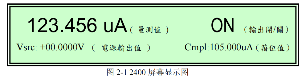
Screen Display: As shown in Figure 2-1, the upper left of the screen displays "Measurement Value", the upper right displays "Output On/Off", the lower left displays "Power Output Value", and the lower right displays "Clamping Value".
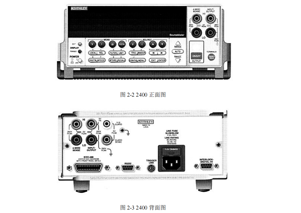
Power: Power switch
MEAS Selection Key: Selects the signal to be measured.
(1) V Measure voltage
(2) I Measure current
(3) Ω Measurement of resistance
(4) FCTN: Measurement of power, compensation resistance, voltage coefficient, ALPHA value, percentage (Initial setting is power).
SOURCE Selection Key: Select the power supply output type.
(1) V Output Voltage
(2) I output current
(3) ▲ and ▼ increase or decrease output value or clamping value (Cmpl).
Operation keys:
(1) EDIT Selects the set power output value or clamping value.
(2) TOGGLE Switches the position of output value and measurement value.
(3) LOCAL cancels the remote computer control and returns to the instrument panel control.
(4) REL Enables/cancels comparison of reference values.
(5) FILTER Enables/disables digital filtering.
(6) LIMIT Enables/cancels limit value test.
(7) TRIG Trigger from the panel to start measurement.
(8) SWEEP Start to output the set scanning voltage or current.
(9) DIGITS Changes the measurement display digits.
(10) SPEED Changes the measurement speed and accuracy.
(11) STORE Sets the number of memories and starts storing.
(12) RECALL Displays the stored measurement values.
(13) CONFIG Setting (together with other buttons, such as CONFIG + SWEEP can set scanning output)
(14) MENU enter to store setting value, change communication mode (IEEE-488 or RS232), or calibration.
(15) EXIT Jump out (16) ENTER Confirmation
RANGE: Range selection
(1) ▲ Change to larger range.
(2) ▼ Change to smaller range.
(3) AUTO automatically switches to the optimum range.
OUTPUT:
(1) ON/OFF 开启/取消电源输出
Operation Introduction
A. Output Voltage, Measurement Current
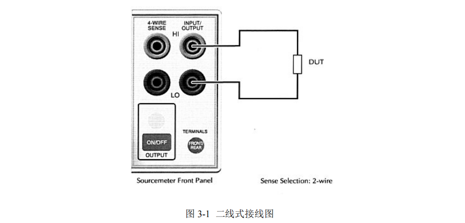
1. Wiring is shown in Fig. 3-1.
2. Press SOURCE V to set the output voltage (change the cursor position by "EDIT" left and right keys, and set the value by "SOURCE" ▲ , ▼ and each numeric key).
3. Press MEAS I to measure current.
4. Press OUTPUT ON/OFF to output. (If you want to measure current only, you can set the voltage to 0V to use as an ammeter.
5. Read the measured value from the panel.
B. Output Current, Measure Voltage
1. Wiring as Figure 3-1.
2. Press SOURCE I to set the output current (change the cursor position by "EDIT" left and right keys, and set the value by "SOURCE" ▲, ▼ and each numeric key).
3. Press MEAS V (Measuring Voltage)
4. Press OUTPUT ON/OFF to output. (Lamp means output)
If you want to measure voltage only, you can set the current to 0A and use it as a voltmeter.
5. Read the measured value from the panel.
C. Measurement of resistance
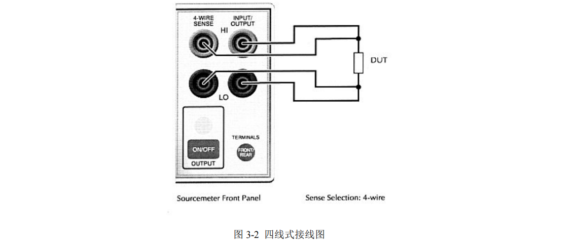
1. For two-wire measurement, the wiring is shown in Figure 3-1; for four-wire measurement, the wiring is shown in Figure 3-2.
2. Press "CONFIG" and then "Ω" to set the resistance measurement, enter "SENSE-MODE" and select 2-wire measurement or 4-wire measurement.
3. Press SOURCE I. 4.
4. Press MEAS Ω.
5. Press OUTPUT ON/OFF to output power.
6. Read the measured value from the panel.
C. Measuring Power
1. Wiring as Fig. 3-1.
2. Press "CONFIG", then "FCTN", select "POWER" and press "ENTER".
3. Press SOURCE I or V. 4.
4. Press MEAS "FCTN". 5.
5. Press OUTPUT ON/OFF to output power.
6. Read the measured value from the panel.
Compensated Resistance (Offset Compensated Ω)

1. Wiring is shown in Figure 3-1.
2. Press "CONFIG", then "FCTN", select "OFF-COMP-OHMS" and press "ENTER".
3. Set I1 and I2. 4.
4. Press SOURCE I.
5. Press "FCTN".
6. Press OUTPUT ON/OFF to output power.
7. Read the measured value from the panel.
D. Measurement of Varistor α (Varistor α)

1. Wiring is shown in Figure 3-1.
2. Press "CONFIG", then "FCTN", select "VAR-ALPHA" and press "ENTER".
3. Set I1 and I2.
4. Press SOURCE I.
5. Press "FCTN". 6.
6. Press OUTPUT ON/OFF to output power.
7. Read the measured value from the panel.
Function:
- Voltage source, current source, voltmeter, ammeter in one new instrument for fast DC tests
- Selectable high voltage (1100V), high current (3A) or high current pulse (10A) power supply/measurements
- Maximum power: 20W (2400 and 2410), 60W (2420), 100W (2430 DC mode), 1kW (2430 Pulse mode) - 5½ digit meter, 0.012% accuracy
- Six-wire ohmic measurement
- Programmable current/voltage with programmable clamping level.
- Programmable current/voltage measurement with clamping level setting. 1000 points/sec.
- Built-in fast pass/fail comparator for automated quality control.
- Digital I/O for direct communication with other instruments
- IEEE-488 and RS-232 interface
- In addition to voltage and current measurement, resistance, power, percentage, Offset Compensated Ω, Varistor α, Voltage Coefficient can also be measured directly.
Panel Profile:
Screen Display: As shown in Figure 2-1, the upper left of the screen displays "Measurement Value", the upper right displays "Output On/Off", the lower left displays "Power Output Value", and the lower right displays "Clamping Value".
Power: Power switch
MEAS Selection Key: Selects the signal to be measured.
(1) V Measure voltage
(2) I Measure current
(3) Ω Measurement of resistance
(4) FCTN: Measurement of power, compensation resistance, voltage coefficient, ALPHA value, percentage (Initial setting is power).
SOURCE Selection Key: Select the power supply output type.
(1) V Output Voltage
(2) I output current
(3) ▲ and ▼ increase or decrease output value or clamping value (Cmpl).
Operation keys:
(1) EDIT Selects the set power output value or clamping value.
(2) TOGGLE Switches the position of output value and measurement value.
(3) LOCAL cancels the remote computer control and returns to the instrument panel control.
(4) REL Enables/cancels comparison of reference values.
(5) FILTER Enables/disables digital filtering.
(6) LIMIT Enables/cancels limit value test.
(7) TRIG Trigger from the panel to start measurement.
(8) SWEEP Start to output the set scanning voltage or current.
(9) DIGITS Changes the measurement display digits.
(10) SPEED Changes the measurement speed and accuracy.
(11) STORE Sets the number of memories and starts storing.
(12) RECALL Displays the stored measurement values.
(13) CONFIG Setting (together with other buttons, such as CONFIG + SWEEP can set scanning output)
(14) MENU enter to store setting value, change communication mode (IEEE-488 or RS232), or calibration.
(15) EXIT Jump out (16) ENTER Confirmation
RANGE: Range selection
(1) ▲ Change to larger range.
(2) ▼ Change to smaller range.
(3) AUTO automatically switches to the optimum range.
OUTPUT:
(1) ON/OFF 开启/取消电源输出
Operation Introduction
A. Output Voltage, Measurement Current
1. Wiring is shown in Fig. 3-1.
2. Press SOURCE V to set the output voltage (change the cursor position by "EDIT" left and right keys, and set the value by "SOURCE" ▲ , ▼ and each numeric key).
3. Press MEAS I to measure current.
4. Press OUTPUT ON/OFF to output. (If you want to measure current only, you can set the voltage to 0V to use as an ammeter.
5. Read the measured value from the panel.
B. Output Current, Measure Voltage
1. Wiring as Figure 3-1.
2. Press SOURCE I to set the output current (change the cursor position by "EDIT" left and right keys, and set the value by "SOURCE" ▲, ▼ and each numeric key).
3. Press MEAS V (Measuring Voltage)
4. Press OUTPUT ON/OFF to output. (Lamp means output)
If you want to measure voltage only, you can set the current to 0A and use it as a voltmeter.
5. Read the measured value from the panel.
C. Measurement of resistance
1. For two-wire measurement, the wiring is shown in Figure 3-1; for four-wire measurement, the wiring is shown in Figure 3-2.
2. Press "CONFIG" and then "Ω" to set the resistance measurement, enter "SENSE-MODE" and select 2-wire measurement or 4-wire measurement.
3. Press SOURCE I. 4.
4. Press MEAS Ω.
5. Press OUTPUT ON/OFF to output power.
6. Read the measured value from the panel.
C. Measuring Power
1. Wiring as Fig. 3-1.
2. Press "CONFIG", then "FCTN", select "POWER" and press "ENTER".
3. Press SOURCE I or V. 4.
4. Press MEAS "FCTN". 5.
5. Press OUTPUT ON/OFF to output power.
6. Read the measured value from the panel.
Compensated Resistance (Offset Compensated Ω)
1. Wiring is shown in Figure 3-1.
2. Press "CONFIG", then "FCTN", select "OFF-COMP-OHMS" and press "ENTER".
3. Set I1 and I2. 4.
4. Press SOURCE I.
5. Press "FCTN".
6. Press OUTPUT ON/OFF to output power.
7. Read the measured value from the panel.
D. Measurement of Varistor α (Varistor α)
1. Wiring is shown in Figure 3-1.
2. Press "CONFIG", then "FCTN", select "VAR-ALPHA" and press "ENTER".
3. Set I1 and I2.
4. Press SOURCE I.
5. Press "FCTN". 6.
6. Press OUTPUT ON/OFF to output power.
7. Read the measured value from the panel.