


Keysight 86100D Yester DCA-X Oscilloscope Performs Optical Conversion


If you want to use the 86100D oscilloscope for optoelectronic conversion, you need to work with the 86105C module, which converts optical signals to electrical signals for testing and analysis.
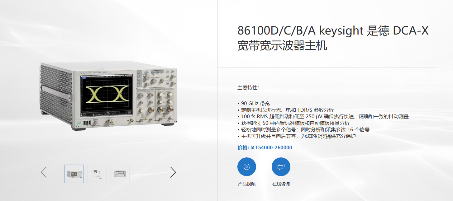
The 86100D DCA-X makes precise measurements of high-speed digital designs from 50MBd to over 80GBd on up to 16 channels simultaneously. Precise measurements of high-speed digital designs from 50MBd to over 80GBd on up to 16 channels.
Model No.: 86100D
Name: Infiniium DCA-X Wide Bandwidth Oscilloscope Mainframe
Brand:KEYSIGHT
Category:General Electronic Test > Oscilloscopes
Product Attributes:Host
You can refer to the following steps:
- Connect the 86105C module to the slot of the 86100D oscilloscope to ensure that the module is properly installed.
- Connect the optical signal source to the 86105C module using the optical fibre interface, taking care to select the appropriate type of optical fibre and wavelength range.
- Turn on the power of 86100D oscilloscope and wait for the instrument self-test to complete.
- On the screen of 86100D oscilloscope, select Channel Setup -> Channel 1 -> Module 1 to activate Channel 1 and Module 1.
- In the Channel Setup menu, select Filter -> On to turn on the filter function to reduce the effect of noise.
- In the Channel Setup menu, select Scale -> Auto Scale to automatically adjust the vertical scale and offset so that the signal is displayed in the centre of the screen.
- In the Channel Setup menu, select More -> Bandwidth -> Full BW to set the sampler bandwidth to the maximum value to get the highest signal resolution.
- In the Channel Setup menu, select More -> Attenuation -> Auto Atten to set the attenuation factor to auto mode to match the amplitude range of the signal.
- In the Channel Setup menu, select More -> Transducer Factor -> Auto Trans Factor to set the transducer conversion factor to auto mode to display the correct signal unit.
- On the screen of 86100D Oscilloscope, select Timebase Setup -> Timebase Mode -> Normal to set the timebase mode to Normal mode.
- In the Timebase Setup menu, select Scale -> Auto Scale to automatically adjust the horizontal scale and delay amount so that the signal is displayed at the full width of the screen.
- In the Timebase Setup menu, select More -> Jitter Mode -> Off to disable the jitter mode function.
- On the screen of 86100D Oscilloscope, select Trigger Setup -> Trigger Source -> Module 1, Ch 1 to set the trigger source as Channel 1 of Module 1.
- In the Trigger Setup menu, select Level -> Auto Level to adjust the trigger level automatically to make the signal trigger stably.
- In Trigger Setup menu, select Slope -> Positive Edge or Negative Edge to choose the trigger edge as positive or negative edge according to the characteristics of the signal.
- In Trigger Setup menu, select More -> Trigger Mode -> Normal or Auto, according to the stability of the signal, select the trigger mode as Normal Mode or Auto Mode.
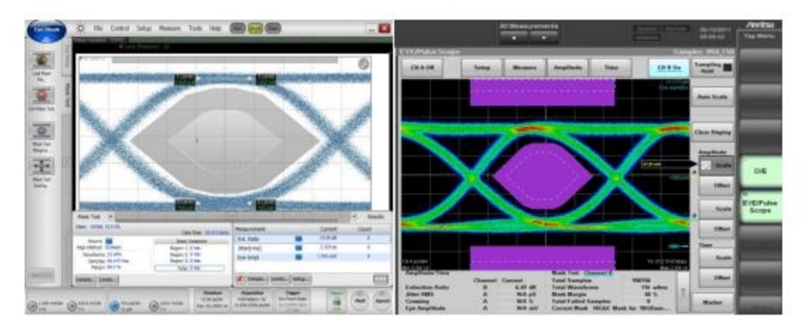
This completes the setup of the photoelectric conversion. You can observe the converted electrical signals on the screen and carry out further analysis and measurement.
If you want to use the 86100D oscilloscope for optoelectronic conversion, you need to work with the 86105C module, which converts optical signals to electrical signals for testing and analysis.
The 86100D DCA-X makes precise measurements of high-speed digital designs from 50MBd to over 80GBd on up to 16 channels simultaneously. Precise measurements of high-speed digital designs from 50MBd to over 80GBd on up to 16 channels.
Model No.: 86100D
Name: Infiniium DCA-X Wide Bandwidth Oscilloscope Mainframe
Brand:KEYSIGHT
Category:General Electronic Test > Oscilloscopes
Product Attributes:Host
You can refer to the following steps:
- Connect the 86105C module to the slot of the 86100D oscilloscope to ensure that the module is properly installed.
- Connect the optical signal source to the 86105C module using the optical fibre interface, taking care to select the appropriate type of optical fibre and wavelength range.
- Turn on the power of 86100D oscilloscope and wait for the instrument self-test to complete.
- On the screen of 86100D oscilloscope, select Channel Setup -> Channel 1 -> Module 1 to activate Channel 1 and Module 1.
- In the Channel Setup menu, select Filter -> On to turn on the filter function to reduce the effect of noise.
- In the Channel Setup menu, select Scale -> Auto Scale to automatically adjust the vertical scale and offset so that the signal is displayed in the centre of the screen.
- In the Channel Setup menu, select More -> Bandwidth -> Full BW to set the sampler bandwidth to the maximum value to get the highest signal resolution.
- In the Channel Setup menu, select More -> Attenuation -> Auto Atten to set the attenuation factor to auto mode to match the amplitude range of the signal.
- In the Channel Setup menu, select More -> Transducer Factor -> Auto Trans Factor to set the transducer conversion factor to auto mode to display the correct signal unit.
- On the screen of 86100D Oscilloscope, select Timebase Setup -> Timebase Mode -> Normal to set the timebase mode to Normal mode.
- In the Timebase Setup menu, select Scale -> Auto Scale to automatically adjust the horizontal scale and delay amount so that the signal is displayed at the full width of the screen.
- In the Timebase Setup menu, select More -> Jitter Mode -> Off to disable the jitter mode function.
- On the screen of 86100D Oscilloscope, select Trigger Setup -> Trigger Source -> Module 1, Ch 1 to set the trigger source as Channel 1 of Module 1.
- In the Trigger Setup menu, select Level -> Auto Level to adjust the trigger level automatically to make the signal trigger stably.
- In Trigger Setup menu, select Slope -> Positive Edge or Negative Edge to choose the trigger edge as positive or negative edge according to the characteristics of the signal.
- In Trigger Setup menu, select More -> Trigger Mode -> Normal or Auto, according to the stability of the signal, select the trigger mode as Normal Mode or Auto Mode.
This completes the setup of the photoelectric conversion. You can observe the converted electrical signals on the screen and carry out further analysis and measurement.