


DSA8300/DSA8200 Sampling Oscilloscopes: 10G/25G/40G/100G Test Solutions


Tektronix DSA8300/DSA8200 Sampling Oscilloscopes Fundamentals and Applications
- Bandwidth up to 80 GHz or more Perform high-speed periodic pulse testing Perform high-speed serial data analysis
- Low noise, high vertical resolution (14 bit) Perform high-speed eye diagram testing and noise analysis.
- Ultra-low trigger jitter (trigger jitter reduced to 200 fs using the 82A04 module) Perform high-speed serial data jitter analysis
What you can do with the Tektronix DSA8300/DSA8200
- S-Parameter Measurements: The DSA8300/DSA8200 enables accurate and repeatable S-parameter measurements, including insertion loss, return loss, group delay, phase and amplitude imbalance, for current and emerging standards with serial data rates from 1 Gb/s to 12.5 Gb/s.
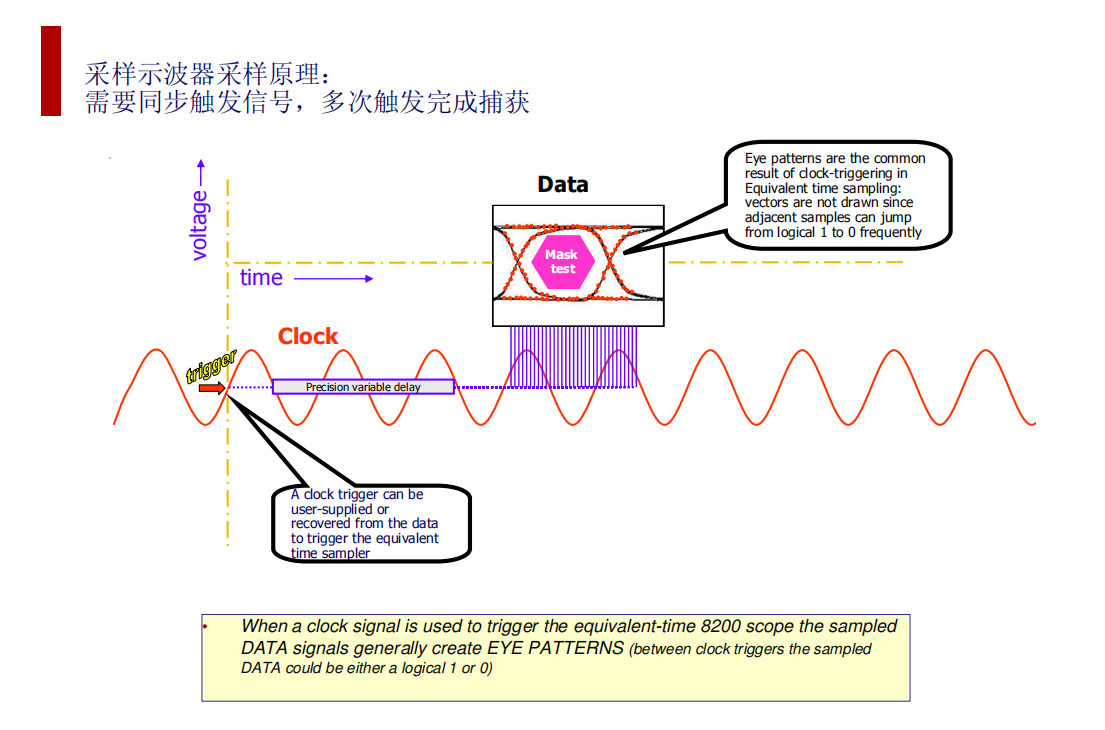
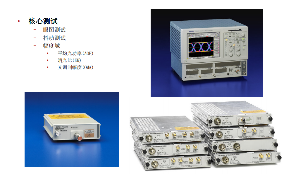
- Eye diagrams and eye diagram contours: The DSA8300/DSA8200 can take advantage of the low noise and high resolution of the 80Cxx family of modules, as well as the advanced algorithms of the 80SJNB software, to acquire and analyse eye diagrams and eye diagram contours of high-speed signals, thereby separating out the individual components of jitter and noise and calculating BERs and three-dimensional eye diagram contours.
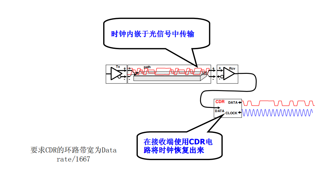
- Clock Recovery: The DSA8300/DSA8200 can use the 80A05 Electrical Clock Recovery Module or the 82A04 Phase Reference Module to clock recover electrical or optical signals and provide internal trigger signals. These modules can support trigger mode and free-run mode, as well as spread spectrum clock (SSC) operation.
- TDR/TDT Measurements: The DSA8300/DSA8200 can use the 80E09 or 80E07 dual-channel TDR/TDT modules to perform time-domain measurements of reflections or transmissions on electrical signals to detect impedance mismatches, crosstalk, transmission line lengths, and other parameters in the signal path.
Optical Interface Physical Layer Testing: Requirements for CRUs
Optical Interface Physical Layer Testing: Noise/Sensitivity Requirements
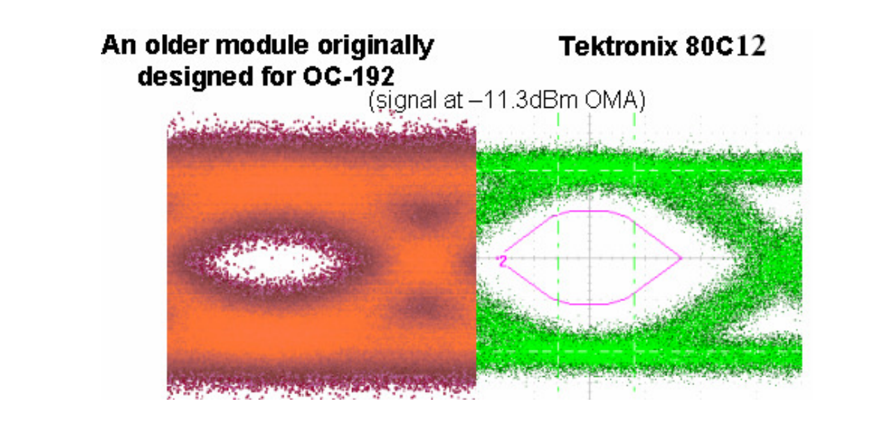
When testing low-power optical modules or ultra-long wavelength optical modules, the optical power of the DUT will be very small. Therefore, the noise of the module must be very low and the sensitivity very high to achieve a certain signal-to-noise ratio, so that the test results can be accurate, and the signal noise shown is really belonging to the signal, not the noise of the module itself.
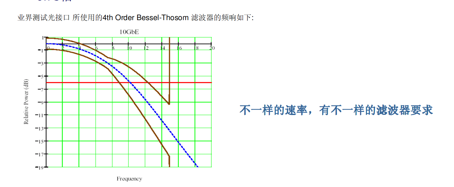
Optical Interface Physical Layer Testing: Filter Requirements
When testing eye diagram templates, an Optical Reference Receiver (O/E + Filter) is required. The signal is first converted optically, and then filtered by a 4th Order Bessel-Thomson filter, whose bandwidth is required by industry specifications to be 0.75 times the rate of the signal under test.
Optical Interface Physical Layer Testing: Wavelength Requirements
- At present, according to the propagation of optical signals in optical fibres, there are single-mode and multi-mode; their wavelengths are also different. The mainstream wavelengths are 780, 850, 1310 and 1550nm.
- Single-mode: 9um fibre diameter, wavelength of 1310, 1550nm
- Multimode: 62.5um fibre diameter, wavelengths are mostly 780, 850nm.
Tektronix 10G/25G/40G/100G test solution ---- module overview
155 Mb/s to 12+ Gb/s Optical Test
80C07B 2.5 GHz BroadWavelength Multirate 155 Mb/s to 2.5 Gb/s Optical Module
80C12 Up to 10GHzBroadWavelengthMultirate 1 Gb/s to 10 Gb/s Optical Module
80C08C 10 GHz Broad Wavelength Multirate 10 Gb/s Optical Module
80C11 30 GHz Long Wavelength Multirate 10 Gb/s Optical Module 40 Gb/s and 100 Gb/s Optical Test 80C10B Multirate Datacom and Telecom 40 Gb/s and 100 Gb/s
10/40/100GbE Optical Compliance testing in ONE Instrument
Tektronix DSA8200/DSA8300 Opt. JNB + 80C08C-CR4 + 80C10B-F1 + 82A04 & 80A06
The only ALL-IN-ONE single instrument solution with:
• All reference receiver Filters from 8.5Gb/s thru 44.5Gb/s
• Highest repeatability & best sensitivity
• Integrated Clock Recovery @ 10G
• SMF and MMF support @ 10G
• 200 fs RMS timebase stability
• 4x fast acquisition throughput over alternative
• Jitter, Noise, and BER Analysis • Calibrated Extinction-Ratio measurements @ 10G
• Differential electrical 50 GHz optional (no module swap needed)
Tektronix DSA8300/DSA8200 Sampling Oscilloscopes Fundamentals and Applications
- Bandwidth up to 80 GHz or more Perform high-speed periodic pulse testing Perform high-speed serial data analysis
- Low noise, high vertical resolution (14 bit) Perform high-speed eye diagram testing and noise analysis.
- Ultra-low trigger jitter (trigger jitter reduced to 200 fs using the 82A04 module) Perform high-speed serial data jitter analysis
What you can do with the Tektronix DSA8300/DSA8200
- S-Parameter Measurements: The DSA8300/DSA8200 enables accurate and repeatable S-parameter measurements, including insertion loss, return loss, group delay, phase and amplitude imbalance, for current and emerging standards with serial data rates from 1 Gb/s to 12.5 Gb/s.
- Eye diagrams and eye diagram contours: The DSA8300/DSA8200 can take advantage of the low noise and high resolution of the 80Cxx family of modules, as well as the advanced algorithms of the 80SJNB software, to acquire and analyse eye diagrams and eye diagram contours of high-speed signals, thereby separating out the individual components of jitter and noise and calculating BERs and three-dimensional eye diagram contours.
- Clock Recovery: The DSA8300/DSA8200 can use the 80A05 Electrical Clock Recovery Module or the 82A04 Phase Reference Module to clock recover electrical or optical signals and provide internal trigger signals. These modules can support trigger mode and free-run mode, as well as spread spectrum clock (SSC) operation.
- TDR/TDT Measurements: The DSA8300/DSA8200 can use the 80E09 or 80E07 dual-channel TDR/TDT modules to perform time-domain measurements of reflections or transmissions on electrical signals to detect impedance mismatches, crosstalk, transmission line lengths, and other parameters in the signal path.
Optical Interface Physical Layer Testing: Requirements for CRUs
Optical Interface Physical Layer Testing: Noise/Sensitivity Requirements
When testing low-power optical modules or ultra-long wavelength optical modules, the optical power of the DUT will be very small. Therefore, the noise of the module must be very low and the sensitivity very high to achieve a certain signal-to-noise ratio, so that the test results can be accurate, and the signal noise shown is really belonging to the signal, not the noise of the module itself.
Optical Interface Physical Layer Testing: Filter Requirements
When testing eye diagram templates, an Optical Reference Receiver (O/E + Filter) is required. The signal is first converted optically, and then filtered by a 4th Order Bessel-Thomson filter, whose bandwidth is required by industry specifications to be 0.75 times the rate of the signal under test.
Optical Interface Physical Layer Testing: Wavelength Requirements
- At present, according to the propagation of optical signals in optical fibres, there are single-mode and multi-mode; their wavelengths are also different. The mainstream wavelengths are 780, 850, 1310 and 1550nm.
- Single-mode: 9um fibre diameter, wavelength of 1310, 1550nm
- Multimode: 62.5um fibre diameter, wavelengths are mostly 780, 850nm.
Tektronix 10G/25G/40G/100G test solution ---- module overview
155 Mb/s to 12+ Gb/s Optical Test
80C07B 2.5 GHz BroadWavelength Multirate 155 Mb/s to 2.5 Gb/s Optical Module
80C12 Up to 10GHzBroadWavelengthMultirate 1 Gb/s to 10 Gb/s Optical Module
80C08C 10 GHz Broad Wavelength Multirate 10 Gb/s Optical Module
80C11 30 GHz Long Wavelength Multirate 10 Gb/s Optical Module 40 Gb/s and 100 Gb/s Optical Test 80C10B Multirate Datacom and Telecom 40 Gb/s and 100 Gb/s
10/40/100GbE Optical Compliance testing in ONE Instrument
Tektronix DSA8200/DSA8300 Opt. JNB + 80C08C-CR4 + 80C10B-F1 + 82A04 & 80A06
The only ALL-IN-ONE single instrument solution with:
• All reference receiver Filters from 8.5Gb/s thru 44.5Gb/s
• Highest repeatability & best sensitivity
• Integrated Clock Recovery @ 10G
• SMF and MMF support @ 10G
• 200 fs RMS timebase stability
• 4x fast acquisition throughput over alternative
• Jitter, Noise, and BER Analysis • Calibrated Extinction-Ratio measurements @ 10G
• Differential electrical 50 GHz optional (no module swap needed)