


86100D oscilloscope usage. 86100D is a digital communication system tester based on sampling signal analysis technology, which is mainly applied to the design, testing and verification of high-speed serial data transmission systems. The following will introduce the use of the 86100D oscilloscope in detail.
first, 86100D oscilloscope main features
86100D oscilloscope has the following main features:
Support all data rate testing from 50 Mb/s to 80 Gb/s range;
Can implement a variety of optical and electrical interfaces, such as SFP +, QSFP +, DDR3, USB, HDMI, etc.;
High precision noise analysis and auto-calibration function.
Based on the above features, the following aspects need to be noted when using the 86100D oscilloscope for digital communication system testing:
Determine the test requirements: including the rate range of the device under test, interface type, test mode, test quantization error requirements, etc.;
Connecting the equipment: according to the interface type of the device under test, select the corresponding connection mode and use the correct connection cable;
Set oscilloscope parameters: set up oscilloscope related parameters, including time, voltage scale, trigger source, etc. through the front panel enabling interface or remote control (such as LabVIEW);
Start the test: start the device under test and begin the test;
Analyze test results: Evaluate test results by oscilloscope display, judge whether they meet the requirements, and adjust parameters or the device under test in time.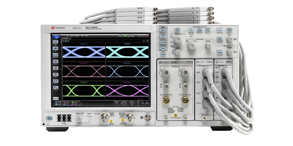
Second, the use of 86100D oscilloscope steps
The following are the detailed steps for using the 86100D oscilloscope:
1. Connect the device under test
According to the interface type and signal characteristics of the device under test, select the correct connection line and connection method, and connect the device under test to the oscilloscope. Note the need to follow the corresponding operating instructions of the device under test for accurate and stable connection.
2. Set the trigger source
In the high-speed serial data transmission system test, the trigger source setting is very critical and has a great impact on the test results. When setting the trigger source, it is necessary to take into account the characteristics of the data sent by the device under test, such as data clock, differential signal, etc., which can be set through the front panel of the oscilloscope or remote control software LabVIEW, etc.
3. Set the time and voltage scale
When setting the time and voltage scales, it is necessary to take into account the characteristics of the frequency and amplitude of the data sent by the device under test. If you cannot find the signal in the viewport, you need to change the time scale and try to expand the viewport range; if the signal amplitude is very small, you need to adjust the voltage scale of the oscilloscope appropriately.
4. Execute start mode and trigger setting
After the oscilloscope starts, you need to set its start mode and trigger settings. Usually, select "single" mode for testing, and set the trigger source to the clock signal sent by the device under test.
5. Analysis of test results
After completing the above steps, the oscilloscope can begin to test the system under test. This part of work can be operated through the front panel of the oscilloscope or LabVIEW and other remote control platforms. Through the visual interface, you can visually observe the signal quality, find the problem points and make adjustments.
III. Cautions
When using the 86100D oscilloscope for digital communication system testing, the following aspects need to be noted:
Connection method: to ensure test accuracy, the appropriate connection method should be selected according to the properties of the device under test, including optical and electrical interfaces, etc;
Test frequency range: need to match the signal frequency of the device under test, otherwise the problem cannot be effectively detected;
trigger threshold: correct setting of the trigger threshold can ensure the integrity of the signal for better analysis;
Guard against accumulation and noise: when performing high-speed digital transmission tests, the media close to the oscilloscope (such as connecting wires) will create scattering and reflection at the frequency of simultaneous transmission. The phenomenon does not cause obvious problems, but if the frequency is comparable, it can lead to phenomena such as jumping in the rhythmical nature.
IV. Summary
Through the above introduction, I believe you have understood the use of the 86100D oscilloscope. When using, you need to select the appropriate connection according to the properties of the device under test, and ensure that the trigger threshold, time/voltage scale and start mode set are correct. Finally, according to the test results and display information, adjust the system to determine whether its performance meets the requirements.