Changes in Fiber Optic Link Testing Techniques from 10G to 40G/100G MPOs
Technology changes life, and informationization is the major trend of development in today's world. The Internet of Things, cloud computing, big data and other emerging network information technology continues to innovate and apply, and in the mobile Internet technology, 3G network is becoming more and more mature, 4GLTE network from last year has been in the country's pilot run, mobile Internet speed will be on a new level. In this era of information industrialization, the city we work and live in is also transforming into a smart city, and various network applications are closely related to us. Whether it is the application of emerging technologies or the construction of a smart city, applications are inseparable from the basic network. The construction of the basic network is based on the site, active terminals and interconnection equipment, as well as the basic interconnection channel to build the network - cabling system. Cabling system needs to be installed in the field construction, susceptible to environmental, product quality, installation process and other factors, is the most important link to determine the quality of network transmission. The reliability of the cabling system not only depends on the quality supervision in the project, but also the last gate, the site acceptance test.
The urgency of the development of testing technology
At present, most of the small and medium-sized cabling projects are still using 10Gb/s as the backbone to realize the Gigabit-to-desktop network architecture. However, with the rapid development of 3G/4G and Internet services, the bandwidth is no longer able to meet the needs of the application, and the use of 40G/100G for the backbone link has become an inevitable trend in the construction of large-scale cabling projects, especially enterprise data centers and Internet IDC data center projects. According to IDC market report, it is expected that after 2015, 40G/100G will gradually become the mainstream port rate.
Since IEEE released the 40G/100G standard for 802.3ba in June 2010, the 40G/100G network is mainly based on experimental network, with low requirements for field testing. After more than 2 years of system development and testing, the current 40G/100G transmission technology is becoming more mature, the major vendors have launched 40G/100G switching and routing equipment, telecom-grade long-distance backbone links using single-mode fiber system, while buildings and data centers of the integrated wiring system is mainly for short-distance transmission of multi-mode OM3/OM4 fiber system based on the use of 12-core MPO connectors. Four-channel / ten-channel pre-connected fiber optic cable. Pre-connected fiber optic cable greatly reduces the installation time and labor costs, but how to quickly identify the fiber optic polarity, fast and accurate test link attenuation has become the primary problem of field testing.
Traditional Fiber Testing Techniques
First of all, let's review the original Gigabit, 10 Gigabit fiber optic link test technology. 2003, TIA-526-14-A multimode fiber optic cable installation optical intensity loss test standard formally defined CPR (CoupledPowerRatio) optical coupling rate test method, the light source is divided into five levels (the following figure), the LED light source is the light source of the level 1, the VCSEL vertical cavity emitting laser light source, the VCSEL vertical cavity emitting laser light source is the light source of the level 1, the VCSEL vertical cavity emitting laser light source is the light source of the level 1. VCSEL Vertical Cavity Surface Emitting Laser (VCSEL VSEL) light source is between class 3 and class 4, and FP laser light source is equivalent to class 5 light source. At the same time, further improve the optical loss test limit value, 1000BASE-SX applied to the OM1 fiber maximum loss value of 2.6dB; 10GBASE-SR applied to the OM3 fiber maximum loss value of 2.6dB. The standard as a general standard for fiber optic link testing, not for specific network applications, emphasizing the detection of the normal state of the transmission of optical signals, it is recommended that the use of LED light source to test multimode fiber links, this way can detect the worst case scenario of fiber links. The laser optimized VCSEL light source is used to detect the link of specific network applications, such as active equipment using VCSEL light source or the current network is ready to upgrade the use of VCSEL light source, the fiber optic loss value obtained from this test is closer to the real loss value of network applications.
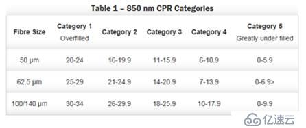
The TIA-526-14-A standard is referenced by several related test standards, such as ANSI/TIA/EIA-568-B, ISO/IEC11801, and ISO/IEC14763-3. And ANSI/TIA/EIA568-B.1.7.1 and ISO/IEC14763-36.22 also specifies the size and use of spools using 50/62.5um multimode fiber. The spool acts as a mode filter by coiling the optical fiber to reduce the high secondary modes generated by the light source in the fiber optic cable, and at the same time reduces the variability of test results caused by the use of different light sources and improves the stability and repeatability of multimode fiber testing.
10GMPO multi-core fiber test model
Compared with the traditional use of LC, SC, ST and other connectors for dual-core optical fiber, the use of MPO connectors can support at least 12-core optical fiber, MPO connectors are mainly used in pre-connecting fiber optic cables. Because MPO fiber exists 12-core channel, TIA-568-C.0-2009B.4 analyzes the channel polarity in detail, for duplex transmission, there are mainly three kinds of A, B, C polarity connection. All three ways are for a common goal ---- to create an end-to-end optical transceiver channel, but the three ways are not compatible, respectively, using different polarity connectors and adapters. For the compatibility and consistency of the whole link, try to consider using connectors and adapters with the same polarity, for example, the polarity of the patch cords used are all A-B, and the types of adapters are all KEYUP-KEYUP, otherwise the different polarity will result in the use of confusion, and it is easy to install the error, resulting in link failure. Therefore, 10G Fibre Channel, MPO backbone link polarity is mainly used in the class C mode (see figure below), the two ports at both ends of the corresponding digital number of internal interoperability, the optical channel is used in groups of two, cross-connections, such as 1 - 2, 2 - 1, the formation of a full-duplex transceiver channel. The left and right ends are converted into LC interfaces through MPO to LC module boxes, and then connected to the equipment through LC patch cords, which are mainly used in data center high-density cabling systems.
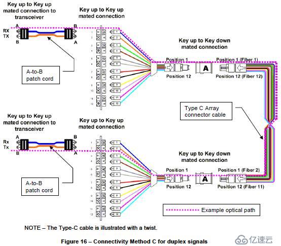
Link under test:

Schematic diagram of the backbone link with MPO-LCA module (MPO1-12 ports correspond to LC1-12 ports one by one) at both ends
1) Setting up the reference: Use one LC-LC test jumper to connect the light source output port (LC) and power meter input port (LC) of the tester.
2)Pull out the optical power meter input port jumper, access another test jumper.
3)Access the tested optical fiber (MTP-LC module box at both ends, and MTP-MTP pre-connected fiber optic cable in the middle), and connect the LC test jumper to the A module at both ends respectively, one end is 1 port, and the other end is connected to 2 ports.
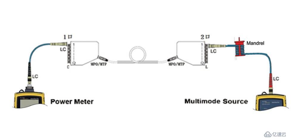
4) Record and save the current loss value of the tested fiber channel, then replace the LC jumper at the light source end to the 2 ports of the A module, and the LC jumper at the optical power meter end to the 1 port of the A module on the other side, and record and save it until the completion of the loss test for 12 channels.

40G/100G MPO multi-core fiber testing technology
In 2010, 802.3ba promulgated the link standards for 40G/100G as 40GBASE-SR4 and 100GBASE-SR10, respectively; MPO connectors and adapters are used; the maximum transmission distance of OM3 fiber is 100 meters, and the maximum loss value is 1.9 dB; the maximum transmission distance of OM4 fiber is 150 meters, and the maximum loss value is 1.5 dB. 40G/100G links are mainly used for data center heavy traffic data transmission. dB. 40G/100G links are mainly used in data centers for high-traffic data transmission, and according to third-party statistics, 88% of the backbone links in data centers are no more than 100 meters long. Therefore, OM3/OM4-based MPO pre-connected fiber optic cables will be the first choice for 40G/100G links. Previously defined thresholds for 10G fiber link testing, such as 0.75dB for LC connectors, allowing the presence of multiple connectors (greater than two), and 0.3dB for fusion splice points are no longer applicable. The new 40G/100G fiber optic backbone link will use pre-connected fiber optic cables, no fusion point and connectors in the link, only need to take into account the loss of MPO connectors at both ends and the loss of the fiber optic cable itself, as far as possible to reduce connector loss, to ensure that the attenuation value of the entire link in the requirements of the new standard.
The two key factors affecting 40G/100G transmission are the light source and fiber optic link loss. More stringent loss requirements on the traditional LED light source test method presents a challenge, the original LED light source output power is low, the divergence angle is large, the connector loss is large, the use of overfull injection (OFL-OverFilledLaunch) way. And the use of VCSEL light source of limited injection method (UFL-UnderFilledLaunch), the near-field intensity of the light channel is concentrated in the center of the range, in the center of the optical fiber transmission mode is less, the divergence angle is smaller, and effectively solves the drawbacks of the LED light source. However, the original IEEE802.3, ANSI/TIA and ISO/IEC and other related standards are only for the definition of the LED light source, while taking into account the price factor, and different manufacturers of VCSEL optical power distribution of large differences, so for the test of 40G/100G of the new standard does not use the definition of the VCSEL light source. Similarly, ISO/IEC14763-3 issued in 2006 defines the method of MPD (ModalPowerDistribution) modal power distribution, which also fails to meet the needs of 40G/100G transmission, although the coupling strength is improved by waveguide arrays.
In October 2010, ANSI/TIA-526-14-B replaced ANSI/TIA-526-14-A, defining the test method for EF (EncircledFlux) light source ring flux, which is also defined in the IEC61280-4-1 standard. EF limits the emission conditions of multimode light sources through a mode regulator, filters the highly submodulated The optical signal is filtered out by a mode conditioner, and a patch cord with a surrogate EF controller is used in place of the original normal test patch cord that uses a multimode spool (as shown below). When the fiber connector under test and the test equipment connector are the same, 1 or 3 test jumpers can be used; when the fiber connector under test and the test equipment connector are different, 3 test jumpers are used; the test jumper should be at least 2 meters and not more than 10 meters. Ring flux can reduce loss measurement deviation from the original ±40% to ±10%, thus reducing measurement uncertainty and improving the repeatability of each measurement.
40G/100G MPO fiber optic test model
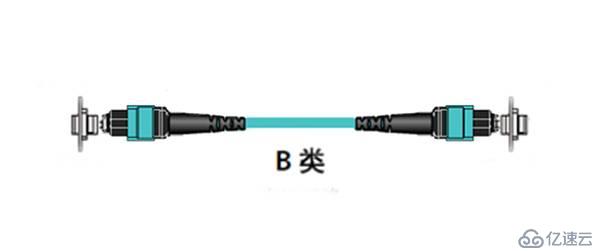
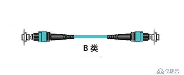
A standard MPO/MTP link consists of two MPO patch cords at each end, two MPO adapters, and a pre-connected backbone fiber optic cable for the MPO. In TIA-568-C.0-2009B.4, both A and B are given for parallel multichannel transmission (see the figure below, Table5).

In order to guarantee the compatibility and singularity of the link, the construction and maintenance are more convenient, especially the MPO patch cords that are often plugged and replaced, in 40G/100G cabling systems, Mode B will be adopted more often. 40G and 100G have different numbers of channels, but their transmission link models are the same, and they both use MPO/MTP interfaces for end-to-end transmission. Therefore, let's take 40G single-channel transmission as an example. When testing, you need to pay attention to the port port type of the pre-connected fiber optic cables and patch cords ---- with guide pins (male) and without guide pins (female).
MPO link under test (female-female):
Traditional MPO multi-core fiber test model ---- using LC interface light source and optical power meter
1) Setting up the reference:Use 3 sections of fiber optic patch cords and 2 LC adapters to set up the reference, and use a multimode spool at the output port end of the light source, as shown in the figure below.
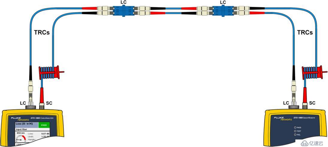
2) Remove the LC short jumper between the two LC adapters in the middle, and add 2 LC-MPO (male) multi-core short jumper cables respectively, connecting the 1st pair of LCs for testing the MPO ports 1,2, as shown in the figure below.
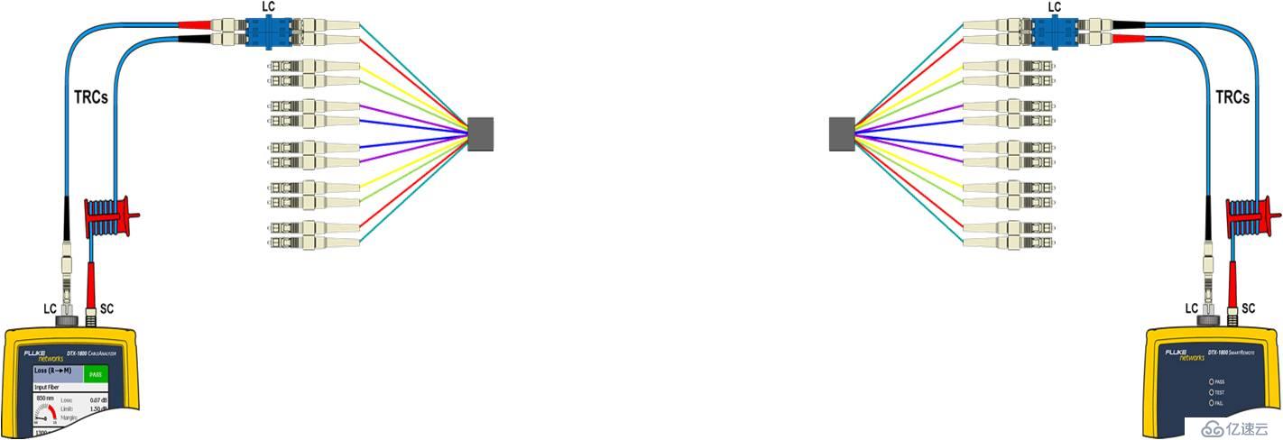
3) Access the MPO fiber optic link under test, perform the test, derive the MPO port 1,2 attenuation value and save it.
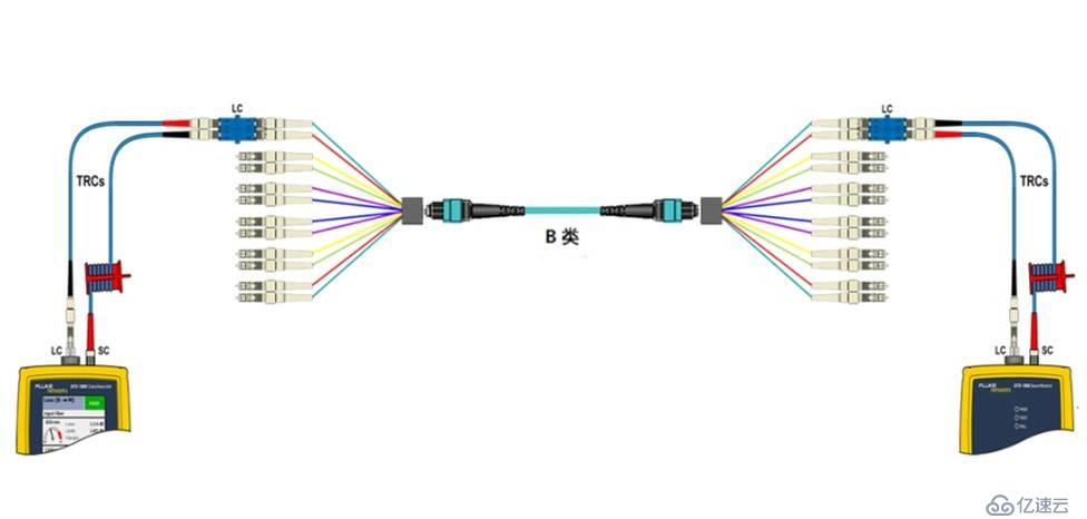
4) Disconnect both ends of the LC adapter and multi-core LC-MPO (male) jumper, according to Class B polarity for the remaining 5 pairs of link attenuation test.
It can be seen that the use of LC interfaces for light sources and optical power for 40G/100G link test, you need to MPO to LC sector patch cords, light source output port terminated patch cords must be with a multimode spool, and each test channel needs to be benchmarked. Therefore, this method is more complicated to operate, and each MPO link needs to be tested 12 times, which consumes more time in large-scale testing.
The latest MPO multi-core fiber test model ---- adopts MPO interface light source and optical power meter
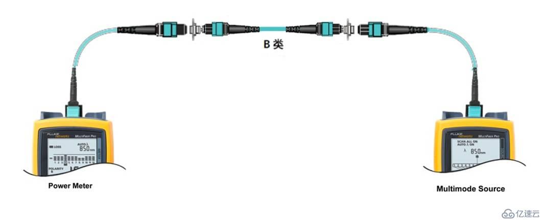
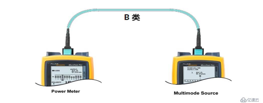
There are already MPO interface fiber field test equipment with EF control light source on the market, which can better meet the field test of MPO fiber links. Using MPO interface adapter and MPO reference jumper, set the corresponding link attenuation threshold, you can one-time benchmark settings and attenuation test for 12 links, automatically detect the polarity of the MPO fiber and issue a report. It is necessary to pay attention to the MPO link connector under test with or without guide pins (male/female), that is, no guide pins on both ends (female-female), guide pins on both ends (male-male), and guide pins on one end and no guide pins on the other end (male-female) in three cases, and select the appropriate reference jumper for the benchmark setup. The following is the most common MPO fiber optic link model without guide pins at both ends, i.e., both ends are female for testing.
MPO link under test (female-female):

1) Setting the benchmark: Use 1 MPO (male-male) test patch cable to connect the light source and optical power meter for benchmark testing.

2)Disconnect the optical power meter end jumper, and then access a MPO (male-male) test jumper.
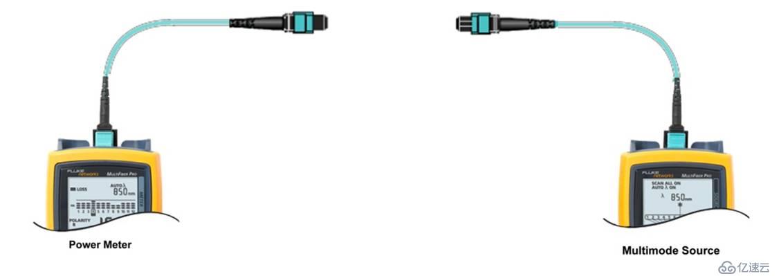
3) Access the tested Class B fiber optic link, perform the test to get the fiber polarity and the loss of 12 channels, and save the test results.

4) Repeat steps 2) to 3) for the next MPO (mother-mother) fiber link test.
The original 10GMPO test model is no longer suitable for future 40G/100G test needs, the LC interface light source and optical power meter leads to a significant increase in the number of times and time to test the MPO fiber optic link, a 12-core MPO backbone link complete test takes nearly ten minutes, and the test stability is poor. Therefore, it is necessary to use test instruments with MPO interfaces for testing. At the same time, EF ring flux control instead of multimode spooling, increasing the stability and reliability of the fiber link test. 100G transmission using ten-channel receive and ten-channel transmit mode is more complex, IEEEP802.3bm40G/100G working group will be on the 100G transmission mode to improve the original ten-channel send and receive mode will be replaced by four-channel. As the next generation of 40G/100G, up to 400G Ethernet transmission standard will be launched next year, it is expected that the use of OM4 fiber. MPO interface fiber optic links in the future deployment will become more and more widespread, is no longer limited to telecom carriers and data centers, and other high-end users, to understand the MPO fiber optic link transmission model and test technology will help us better manage the future of 40G/100G high-speed communication transmission channel. 100G high-speed communication transmission channel.
Technology changes life, and informationization is the major trend of development in today's world. The Internet of Things, cloud computing, big data and other emerging network information technology continues to innovate and apply, and in the mobile Internet technology, 3G network is becoming more and more mature, 4GLTE network from last year has been in the country's pilot run, mobile Internet speed will be on a new level. In this era of information industrialization, the city we work and live in is also transforming into a smart city, and various network applications are closely related to us. Whether it is the application of emerging technologies or the construction of a smart city, applications are inseparable from the basic network. The construction of the basic network is based on the site, active terminals and interconnection equipment, as well as the basic interconnection channel to build the network - cabling system. Cabling system needs to be installed in the field construction, susceptible to environmental, product quality, installation process and other factors, is the most important link to determine the quality of network transmission. The reliability of the cabling system not only depends on the quality supervision in the project, but also the last gate, the site acceptance test.
The urgency of the development of testing technology
At present, most of the small and medium-sized cabling projects are still using 10Gb/s as the backbone to realize the Gigabit-to-desktop network architecture. However, with the rapid development of 3G/4G and Internet services, the bandwidth is no longer able to meet the needs of the application, and the use of 40G/100G for the backbone link has become an inevitable trend in the construction of large-scale cabling projects, especially enterprise data centers and Internet IDC data center projects. According to IDC market report, it is expected that after 2015, 40G/100G will gradually become the mainstream port rate.
Since IEEE released the 40G/100G standard for 802.3ba in June 2010, the 40G/100G network is mainly based on experimental network, with low requirements for field testing. After more than 2 years of system development and testing, the current 40G/100G transmission technology is becoming more mature, the major vendors have launched 40G/100G switching and routing equipment, telecom-grade long-distance backbone links using single-mode fiber system, while buildings and data centers of the integrated wiring system is mainly for short-distance transmission of multi-mode OM3/OM4 fiber system based on the use of 12-core MPO connectors. Four-channel / ten-channel pre-connected fiber optic cable. Pre-connected fiber optic cable greatly reduces the installation time and labor costs, but how to quickly identify the fiber optic polarity, fast and accurate test link attenuation has become the primary problem of field testing.
Traditional Fiber Testing Techniques
First of all, let's review the original Gigabit, 10 Gigabit fiber optic link test technology. 2003, TIA-526-14-A multimode fiber optic cable installation optical intensity loss test standard formally defined CPR (CoupledPowerRatio) optical coupling rate test method, the light source is divided into five levels (the following figure), the LED light source is the light source of the level 1, the VCSEL vertical cavity emitting laser light source, the VCSEL vertical cavity emitting laser light source is the light source of the level 1, the VCSEL vertical cavity emitting laser light source is the light source of the level 1. VCSEL Vertical Cavity Surface Emitting Laser (VCSEL VSEL) light source is between class 3 and class 4, and FP laser light source is equivalent to class 5 light source. At the same time, further improve the optical loss test limit value, 1000BASE-SX applied to the OM1 fiber maximum loss value of 2.6dB; 10GBASE-SR applied to the OM3 fiber maximum loss value of 2.6dB. The standard as a general standard for fiber optic link testing, not for specific network applications, emphasizing the detection of the normal state of the transmission of optical signals, it is recommended that the use of LED light source to test multimode fiber links, this way can detect the worst case scenario of fiber links. The laser optimized VCSEL light source is used to detect the link of specific network applications, such as active equipment using VCSEL light source or the current network is ready to upgrade the use of VCSEL light source, the fiber optic loss value obtained from this test is closer to the real loss value of network applications.

The TIA-526-14-A standard is referenced by several related test standards, such as ANSI/TIA/EIA-568-B, ISO/IEC11801, and ISO/IEC14763-3. And ANSI/TIA/EIA568-B.1.7.1 and ISO/IEC14763-36.22 also specifies the size and use of spools using 50/62.5um multimode fiber. The spool acts as a mode filter by coiling the optical fiber to reduce the high secondary modes generated by the light source in the fiber optic cable, and at the same time reduces the variability of test results caused by the use of different light sources and improves the stability and repeatability of multimode fiber testing.
10GMPO multi-core fiber test model
Compared with the traditional use of LC, SC, ST and other connectors for dual-core optical fiber, the use of MPO connectors can support at least 12-core optical fiber, MPO connectors are mainly used in pre-connecting fiber optic cables. Because MPO fiber exists 12-core channel, TIA-568-C.0-2009B.4 analyzes the channel polarity in detail, for duplex transmission, there are mainly three kinds of A, B, C polarity connection. All three ways are for a common goal ---- to create an end-to-end optical transceiver channel, but the three ways are not compatible, respectively, using different polarity connectors and adapters. For the compatibility and consistency of the whole link, try to consider using connectors and adapters with the same polarity, for example, the polarity of the patch cords used are all A-B, and the types of adapters are all KEYUP-KEYUP, otherwise the different polarity will result in the use of confusion, and it is easy to install the error, resulting in link failure. Therefore, 10G Fibre Channel, MPO backbone link polarity is mainly used in the class C mode (see figure below), the two ports at both ends of the corresponding digital number of internal interoperability, the optical channel is used in groups of two, cross-connections, such as 1 - 2, 2 - 1, the formation of a full-duplex transceiver channel. The left and right ends are converted into LC interfaces through MPO to LC module boxes, and then connected to the equipment through LC patch cords, which are mainly used in data center high-density cabling systems.

Link under test:

Schematic diagram of the backbone link with MPO-LCA module (MPO1-12 ports correspond to LC1-12 ports one by one) at both ends
1) Setting up the reference: Use one LC-LC test jumper to connect the light source output port (LC) and power meter input port (LC) of the tester.

2)Pull out the optical power meter input port jumper, access another test jumper.
3)Access the tested optical fiber (MTP-LC module box at both ends, and MTP-MTP pre-connected fiber optic cable in the middle), and connect the LC test jumper to the A module at both ends respectively, one end is 1 port, and the other end is connected to 2 ports.

4) Record and save the current loss value of the tested fiber channel, then replace the LC jumper at the light source end to the 2 ports of the A module, and the LC jumper at the optical power meter end to the 1 port of the A module on the other side, and record and save it until the completion of the loss test for 12 channels.

40G/100G MPO multi-core fiber testing technology
In 2010, 802.3ba promulgated the link standards for 40G/100G as 40GBASE-SR4 and 100GBASE-SR10, respectively; MPO connectors and adapters are used; the maximum transmission distance of OM3 fiber is 100 meters, and the maximum loss value is 1.9 dB; the maximum transmission distance of OM4 fiber is 150 meters, and the maximum loss value is 1.5 dB. 40G/100G links are mainly used for data center heavy traffic data transmission. dB. 40G/100G links are mainly used in data centers for high-traffic data transmission, and according to third-party statistics, 88% of the backbone links in data centers are no more than 100 meters long. Therefore, OM3/OM4-based MPO pre-connected fiber optic cables will be the first choice for 40G/100G links. Previously defined thresholds for 10G fiber link testing, such as 0.75dB for LC connectors, allowing the presence of multiple connectors (greater than two), and 0.3dB for fusion splice points are no longer applicable. The new 40G/100G fiber optic backbone link will use pre-connected fiber optic cables, no fusion point and connectors in the link, only need to take into account the loss of MPO connectors at both ends and the loss of the fiber optic cable itself, as far as possible to reduce connector loss, to ensure that the attenuation value of the entire link in the requirements of the new standard.
The two key factors affecting 40G/100G transmission are the light source and fiber optic link loss. More stringent loss requirements on the traditional LED light source test method presents a challenge, the original LED light source output power is low, the divergence angle is large, the connector loss is large, the use of overfull injection (OFL-OverFilledLaunch) way. And the use of VCSEL light source of limited injection method (UFL-UnderFilledLaunch), the near-field intensity of the light channel is concentrated in the center of the range, in the center of the optical fiber transmission mode is less, the divergence angle is smaller, and effectively solves the drawbacks of the LED light source. However, the original IEEE802.3, ANSI/TIA and ISO/IEC and other related standards are only for the definition of the LED light source, while taking into account the price factor, and different manufacturers of VCSEL optical power distribution of large differences, so for the test of 40G/100G of the new standard does not use the definition of the VCSEL light source. Similarly, ISO/IEC14763-3 issued in 2006 defines the method of MPD (ModalPowerDistribution) modal power distribution, which also fails to meet the needs of 40G/100G transmission, although the coupling strength is improved by waveguide arrays.
In October 2010, ANSI/TIA-526-14-B replaced ANSI/TIA-526-14-A, defining the test method for EF (EncircledFlux) light source ring flux, which is also defined in the IEC61280-4-1 standard. EF limits the emission conditions of multimode light sources through a mode regulator, filters the highly submodulated The optical signal is filtered out by a mode conditioner, and a patch cord with a surrogate EF controller is used in place of the original normal test patch cord that uses a multimode spool (as shown below). When the fiber connector under test and the test equipment connector are the same, 1 or 3 test jumpers can be used; when the fiber connector under test and the test equipment connector are different, 3 test jumpers are used; the test jumper should be at least 2 meters and not more than 10 meters. Ring flux can reduce loss measurement deviation from the original ±40% to ±10%, thus reducing measurement uncertainty and improving the repeatability of each measurement.

40G/100G MPO fiber optic test model
A standard MPO/MTP link consists of two MPO patch cords at each end, two MPO adapters, and a pre-connected backbone fiber optic cable for the MPO. In TIA-568-C.0-2009B.4, both A and B are given for parallel multichannel transmission (see the figure below, Table5).


In order to guarantee the compatibility and singularity of the link, the construction and maintenance are more convenient, especially the MPO patch cords that are often plugged and replaced, in 40G/100G cabling systems, Mode B will be adopted more often. 40G and 100G have different numbers of channels, but their transmission link models are the same, and they both use MPO/MTP interfaces for end-to-end transmission. Therefore, let's take 40G single-channel transmission as an example. When testing, you need to pay attention to the port port type of the pre-connected fiber optic cables and patch cords ---- with guide pins (male) and without guide pins (female).
MPO link under test (female-female):

Traditional MPO multi-core fiber test model ---- using LC interface light source and optical power meter
1) Setting up the reference:Use 3 sections of fiber optic patch cords and 2 LC adapters to set up the reference, and use a multimode spool at the output port end of the light source, as shown in the figure below.

2) Remove the LC short jumper between the two LC adapters in the middle, and add 2 LC-MPO (male) multi-core short jumper cables respectively, connecting the 1st pair of LCs for testing the MPO ports 1,2, as shown in the figure below.

3) Access the MPO fiber optic link under test, perform the test, derive the MPO port 1,2 attenuation value and save it.

4) Disconnect both ends of the LC adapter and multi-core LC-MPO (male) jumper, according to Class B polarity for the remaining 5 pairs of link attenuation test.
It can be seen that the use of LC interfaces for light sources and optical power for 40G/100G link test, you need to MPO to LC sector patch cords, light source output port terminated patch cords must be with a multimode spool, and each test channel needs to be benchmarked. Therefore, this method is more complicated to operate, and each MPO link needs to be tested 12 times, which consumes more time in large-scale testing.
The latest MPO multi-core fiber test model ---- adopts MPO interface light source and optical power meter
There are already MPO interface fiber field test equipment with EF control light source on the market, which can better meet the field test of MPO fiber links. Using MPO interface adapter and MPO reference jumper, set the corresponding link attenuation threshold, you can one-time benchmark settings and attenuation test for 12 links, automatically detect the polarity of the MPO fiber and issue a report. It is necessary to pay attention to the MPO link connector under test with or without guide pins (male/female), that is, no guide pins on both ends (female-female), guide pins on both ends (male-male), and guide pins on one end and no guide pins on the other end (male-female) in three cases, and select the appropriate reference jumper for the benchmark setup. The following is the most common MPO fiber optic link model without guide pins at both ends, i.e., both ends are female for testing.
MPO link under test (female-female):

1) Setting the benchmark: Use 1 MPO (male-male) test patch cable to connect the light source and optical power meter for benchmark testing.

2)Disconnect the optical power meter end jumper, and then access a MPO (male-male) test jumper.

3) Access the tested Class B fiber optic link, perform the test to get the fiber polarity and the loss of 12 channels, and save the test results.

4) Repeat steps 2) to 3) for the next MPO (mother-mother) fiber link test.
The original 10GMPO test model is no longer suitable for future 40G/100G test needs, the LC interface light source and optical power meter leads to a significant increase in the number of times and time to test the MPO fiber optic link, a 12-core MPO backbone link complete test takes nearly ten minutes, and the test stability is poor. Therefore, it is necessary to use test instruments with MPO interfaces for testing. At the same time, EF ring flux control instead of multimode spooling, increasing the stability and reliability of the fiber link test. 100G transmission using ten-channel receive and ten-channel transmit mode is more complex, IEEEP802.3bm40G/100G working group will be on the 100G transmission mode to improve the original ten-channel send and receive mode will be replaced by four-channel. As the next generation of 40G/100G, up to 400G Ethernet transmission standard will be launched next year, it is expected that the use of OM4 fiber. MPO interface fiber optic links in the future deployment will become more and more widespread, is no longer limited to telecom carriers and data centers, and other high-end users, to understand the MPO fiber optic link transmission model and test technology will help us better manage the future of 40G/100G high-speed communication transmission channel. 100G high-speed communication transmission channel.


