


Senior engineers will also ignore these details (oscilloscope how to make good use of?)


What is the trigger mode of the oscilloscope?
Oscilloscope "trigger" is to make the oscilloscope scan and the observed signal synchronization, so as to display a stable waveform. To meet different observation needs, different "trigger modes" are required. The basic trigger mode of the oscilloscope has three kinds:
The first is the "automatic mode (AUTO)":
In this mode, when the trigger does not occur, the oscilloscope scanning system will automatically scan according to the set scan rate;
And when a trigger occurs, the scanning system will try to scan according to the frequency of the signal, so in this mode whether the trigger conditions are met, the oscilloscope will produce a scan, can be seen on the screen with changes in the scan line, which is the characteristics of this mode.
The second is the "normal mode / conventional mode (NORM)":
This mode is different from the automatic mode, the oscilloscope in this mode only when the trigger conditions are met before scanning, if there is no trigger, it does not scan.
Therefore, in this mode, if there is no trigger, for the analog oscilloscope will not see the scan line, nothing on the screen, for the digital oscilloscope will not see the waveform update, do not understand this often think that the signal is not connected to or what other faults.
The third type is "SINGLE mode":
This mode is somewhat similar to the "normal mode", that is, only when the trigger conditions are met to produce a scan, otherwise no scan.
The difference is that the scan is generated and completed, the oscilloscope scanning system that enters a state of rest, even if the signal to meet the conditions of the trigger and no longer scan, that is, the trigger is only one scan, that is, a single, must be manually restarted by the scanning system to produce the next trigger.
Obviously, for ordinary analog oscilloscope in this mode you will often find that nothing can be seen, because the waveform a flash, the oscilloscope can not be retained, in most occasions this mode is not useful. The above three trigger modes are the majority of oscilloscopes will provide.
In practice, how to choose and use it?
In practice, the choice of different trigger modes to be observed based on the characteristics of the signal and the content to be observed to make a judgment, and there is no fixed rule, but often an interactive process, that is, through the choice of different trigger modes to understand the characteristics of the signal, and according to the characteristics of the signal and want to observe the content to choose an effective trigger mode.
The most important thing in this process is to understand the working mechanism of different trigger modes, to understand the characteristics of the observed signal and to clarify the content to be observed.
Generally speaking, when the characteristics of the signal is not very well understood, you should choose automatic mode, because at this time, no matter what kind of signal oscilloscope will scan, you can at least see something on the screen, even if it is just a scan line, and not nothing.
After the scan line can be adjusted by the vertical gain, vertical position, time base rate and other parameters to "find" the waveform, and then stabilize the waveform by selecting the trigger source, trigger edge, trigger level.
For the analog oscilloscope, as long as the signal is periodic, its frequency in the range suitable for the corresponding oscilloscope observation and not too complex, through such steps can generally achieve a general understanding of the signal, and then as needed for further observation.
For the normal mode, many friends may feel that there is no difference in the observation effect with the automatic mode, there is often such a situation, the trigger mode between automatic and normal switch, the screen waveform does not change, but this situation often occurs only in the case of the observed signal is some simple periodic signal.
Normal mode is useful to observe the details of the waveform, especially for more complex signals, such as video synchronization signals. Why is this so?
This is because in order to observe the details, we have to turn up the time base scan rate in order to expand the waveform. When we do so, it will make the observed signal frequency relative to the oscilloscope scan rate becomes low, that is, between the two triggers oscilloscope may be many times the scan.
In this case, if we select the automatic mode, the oscilloscope will actually carry out all these scans, the result is that the waveform corresponding to these scans (they are not generated by the trigger) and the waveform corresponding to the trigger scan are displayed together, resulting in the display of waveform overlap, and therefore can not clearly display the waveform we want to see.
And if we choose the normal mode, these scans between the trigger oscilloscope will not actually carry out, only those scans generated by the trigger, and thus only display the waveform we want to see associated with the trigger, so that the waveform will be clearer, which is the function of the normal trigger mode.
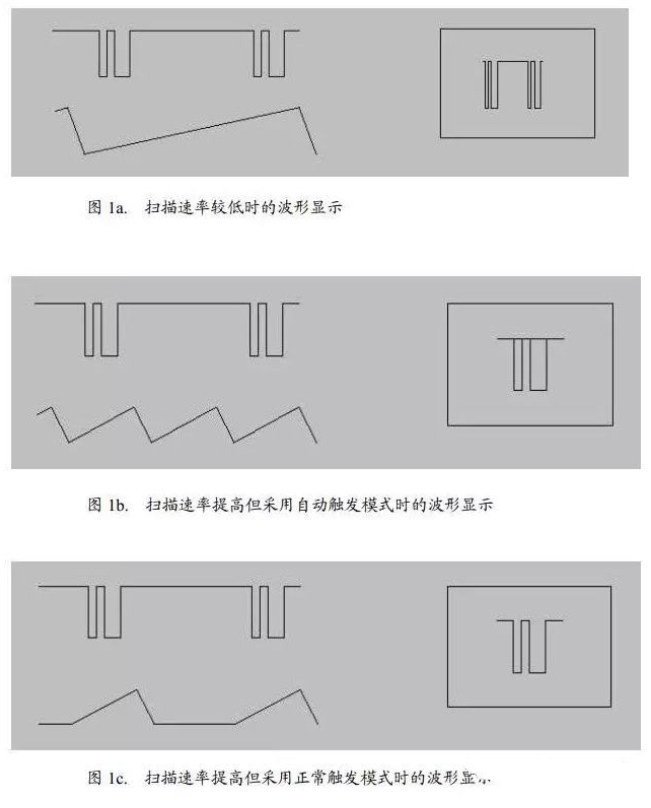
Figure 1 is an illustration of this situation. In Figure 1, the waveform being observed is shown on the upper left side, the scan waveform is shown on the lower side, and the display of the waveform is shown on the right side.
(a) The lower scan rate in Figure 1a does not allow easy observation of the details of the waveform;
(b) Figure 1b increases the scan rate and adopts the auto-trigger mode, when the displayed waveform is unclear and has an overlapping phenomenon;
The scan rate in Figure 1c is the same as that in Figure 1b, but with the normal trigger mode, which scans only when there is a trigger, thus displaying a clear waveform.
Above we briefly described the basic trigger mode of the oscilloscope and their consideration in the practical use, in order to help beginners master the oscilloscope.
In addition to what is discussed in this article, the adjustment of other parameters of the oscilloscope is also very important, and the user should have a clear understanding of the meaning of various parameter adjustments on the one hand.
On the other hand, it is also necessary to understand the characteristics of the observed signal and to clearly observe the target, in order to really use the oscilloscope effectively to achieve the purpose of measurement testing.
How to use a good and live oscilloscope?
For power engineers, once there are problems with the product need to catch the waveform, timing, testing the exact value to help engineers analyze, processing. Speak with facts, look at the waveform to speak. How to make the test data accurate and reliable is very important.
Accurate numbers can help us, while distorted waveforms and values can only mislead us, let us backtrack, let us lose direction and do a lot more useless work.
Think carefully, although they are not so proficient in oscilloscope research, but also read a lot of articles on oscilloscopes, practice encountered a lot of problems, solve a lot of problems, all the way over or a little experience can share with you, I hope you can help. If the writing is not good, please forgive me.
I often see a lot of small companies with oscilloscopes too low-end, low bandwidth, sampling rate bottom, that can catch the waveform on the line, that there is no need to buy so good oscilloscope, and that the oscilloscope operation is simple, not so much specification.
See their operation of the oscilloscope, do not do the test before the preparation, pick it up and use, in fact, that is not correct, may often be the incorrect operation leads to distortion of test results, affecting the analysis. Even some very senior engineers may not pay attention to some details.
Many engineers lack of awareness of the oscilloscope, how to better use the oscilloscope or to be improved. The following I see a lot of engineers often commit the problem to correct, share some of my knowledge.
Many engineers directly pick up the probe on the test, simply do not check whether the probe needs to be compensated, whether the oscilloscope needs to be calibrated. Only in some large companies or trained engineers will do the preparatory work before use. Oscilloscope before use need self-calibration and need probe compensation adjustment, perform this adjustment is to make the probe match the input channel.
1. When operating the instrument for the first time and when displaying data from multiple input channels simultaneously, it may be necessary to calibrate the data in both vertical and horizontal directions to synchronize the time base, amplitude and position. For example, calibration is required when significant temperature changes (> 5°) occur.
Disconnect any probes or cables from the channel input connectors. Make sure the instrument is running and warmed up for a period of time. r the File menu, select Selfalignment.
On the Control tab, click Start Alignment.
R In the alignment state field. The results of each calibration step for each input channel are displayed in the Results tab.
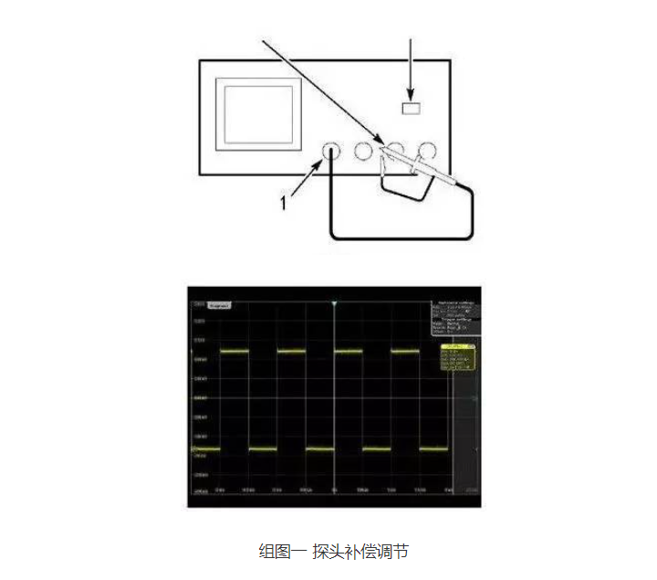
The operation steps for probe compensation adjustment are as follows: 1. Connect the oscilloscope probe to the channel and press the PRESET button on the front panel (in the left panel setup area). Connect the probe signal end and reference ground to the reference output on the oscilloscope panel, then press Autoset. If using the probe hook front attachment, securely attach the signal pin front to the probe to ensure proper connection. As shown in Group Figure 1:
2. Check the shape of the displayed waveform. The possible situations are shown in Figure 2
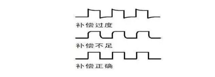
Over and under adjustment of the probe is required. To be able to test the accurate value better.
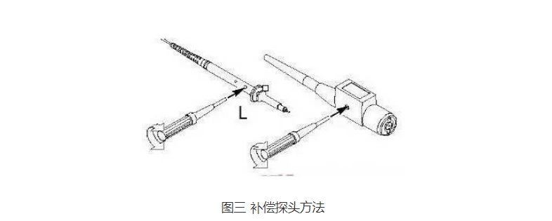
3. If the waveform is not correct, please adjust the probe. As shown in Figure 3 below, until the waveform is the correct waveform for the above compensation.
The above two points may seem simple, but they are often overlooked by engineers. To make the measurement more accurate, please make sure to pay attention to the test. These two calibration functions should be available in any oscilloscope.
2 Test voltage ripple
Many power supply engineers also do not pay as much attention to the ripple measurement when taking the test for granted. The use of different methods of oscilloscopes lead to a wide range of test results. Figure 4 and Figure 5 below, for the same product, the same test point, due to differences in test methods, resulting in large differences in test results. Ripple is an important parameter for the power source, but due to their own operational problems and lead to do the test does not pass, and waste a lot of labor and costs to rectify is not worth it.
Sometimes your customer's use of the instrument and attention is not enough, resulting in the wrong test data. But their side of the product and there is no problem, so that how to say it does not make sense, so much so that customers still think they are cheating them, so the test method is very important. Pay attention to these details, you can save a lot of time and make their ability to go to the next level.
The value of the oscilloscope test itself there are errors (here I will not explain for the time being). Now many companies require the value of the test waveform graph as the basis for determination. In fact, the oscilloscope only tests the voltage change over time, mainly in debugging to capture the waveform. Specific measurement of DC voltage RMS amount of accuracy is not as accurate as the value of the digital multimeter. The DC accuracy of the oscilloscope is also calibrated to the multimeter as a reference. But more and more companies and engineers to the value of the oscilloscope as the real value, then we can only try to do is to test the least error.
The following is a diagram and analysis of the test ripple:
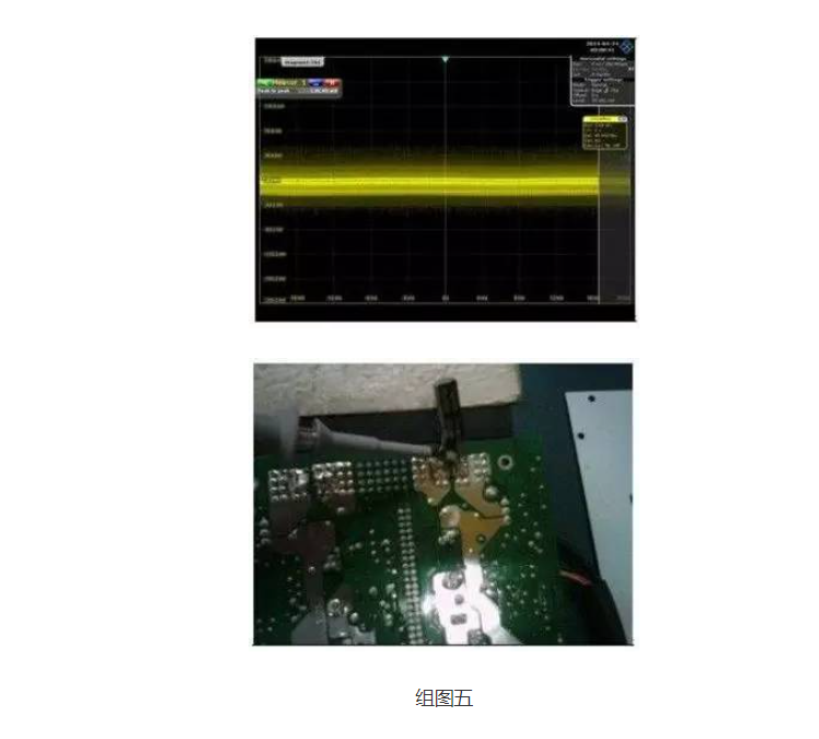
The result value of the test ripple of group figure four 3.9921V is much larger than that of figure five 0.126V, but the test value of group figure four is not true.
Analysis of the problem: In fact, there is no problem with the product. It's just a problem with the test method. Now let's point out the problem points:
Mistake one: the use of a long ground wire.
Mistake two: the probe formed a loop and ground wire are placed near the power transformer and switching components.
Mistake 3: Excess inductance exists between the oscilloscope probe and the output capacitor. Due to these inattention, resulting in picking up a lot of high-frequency signals, the magnetic field of the transformer, the electric field of the switch, so that the waveform caught by the oscilloscope has high-frequency noise mixed in it to show up.
Error 4: The range is too large.
Accurately test ripple need to do: use the bandwidth limit to measure ripple to prevent picking up high-frequency noise that is not really there. An oscilloscope bandwidth setting of 20M is sufficient. Remove the probe "cap" and ground clips to prevent antenna effects from long ground wires. Wrap a near-ground wire between the probe and ground.
What is the trigger mode of the oscilloscope?
Oscilloscope "trigger" is to make the oscilloscope scan and the observed signal synchronization, so as to display a stable waveform. To meet different observation needs, different "trigger modes" are required. The basic trigger mode of the oscilloscope has three kinds:
The first is the "automatic mode (AUTO)":
In this mode, when the trigger does not occur, the oscilloscope scanning system will automatically scan according to the set scan rate;
And when a trigger occurs, the scanning system will try to scan according to the frequency of the signal, so in this mode whether the trigger conditions are met, the oscilloscope will produce a scan, can be seen on the screen with changes in the scan line, which is the characteristics of this mode.
The second is the "normal mode / conventional mode (NORM)":
This mode is different from the automatic mode, the oscilloscope in this mode only when the trigger conditions are met before scanning, if there is no trigger, it does not scan.
Therefore, in this mode, if there is no trigger, for the analog oscilloscope will not see the scan line, nothing on the screen, for the digital oscilloscope will not see the waveform update, do not understand this often think that the signal is not connected to or what other faults.
The third type is "SINGLE mode":
This mode is somewhat similar to the "normal mode", that is, only when the trigger conditions are met to produce a scan, otherwise no scan.
The difference is that the scan is generated and completed, the oscilloscope scanning system that enters a state of rest, even if the signal to meet the conditions of the trigger and no longer scan, that is, the trigger is only one scan, that is, a single, must be manually restarted by the scanning system to produce the next trigger.
Obviously, for ordinary analog oscilloscope in this mode you will often find that nothing can be seen, because the waveform a flash, the oscilloscope can not be retained, in most occasions this mode is not useful. The above three trigger modes are the majority of oscilloscopes will provide.
In practice, how to choose and use it?
In practice, the choice of different trigger modes to be observed based on the characteristics of the signal and the content to be observed to make a judgment, and there is no fixed rule, but often an interactive process, that is, through the choice of different trigger modes to understand the characteristics of the signal, and according to the characteristics of the signal and want to observe the content to choose an effective trigger mode.
The most important thing in this process is to understand the working mechanism of different trigger modes, to understand the characteristics of the observed signal and to clarify the content to be observed.
Generally speaking, when the characteristics of the signal is not very well understood, you should choose automatic mode, because at this time, no matter what kind of signal oscilloscope will scan, you can at least see something on the screen, even if it is just a scan line, and not nothing.
After the scan line can be adjusted by the vertical gain, vertical position, time base rate and other parameters to "find" the waveform, and then stabilize the waveform by selecting the trigger source, trigger edge, trigger level.
For the analog oscilloscope, as long as the signal is periodic, its frequency in the range suitable for the corresponding oscilloscope observation and not too complex, through such steps can generally achieve a general understanding of the signal, and then as needed for further observation.
For the normal mode, many friends may feel that there is no difference in the observation effect with the automatic mode, there is often such a situation, the trigger mode between automatic and normal switch, the screen waveform does not change, but this situation often occurs only in the case of the observed signal is some simple periodic signal.
Normal mode is useful to observe the details of the waveform, especially for more complex signals, such as video synchronization signals. Why is this so?
This is because in order to observe the details, we have to turn up the time base scan rate in order to expand the waveform. When we do so, it will make the observed signal frequency relative to the oscilloscope scan rate becomes low, that is, between the two triggers oscilloscope may be many times the scan.
In this case, if we select the automatic mode, the oscilloscope will actually carry out all these scans, the result is that the waveform corresponding to these scans (they are not generated by the trigger) and the waveform corresponding to the trigger scan are displayed together, resulting in the display of waveform overlap, and therefore can not clearly display the waveform we want to see.
And if we choose the normal mode, these scans between the trigger oscilloscope will not actually carry out, only those scans generated by the trigger, and thus only display the waveform we want to see associated with the trigger, so that the waveform will be clearer, which is the function of the normal trigger mode.
Figure 1 is an illustration of this situation. In Figure 1, the waveform being observed is shown on the upper left side, the scan waveform is shown on the lower side, and the display of the waveform is shown on the right side.
(a) The lower scan rate in Figure 1a does not allow easy observation of the details of the waveform;
(b) Figure 1b increases the scan rate and adopts the auto-trigger mode, when the displayed waveform is unclear and has an overlapping phenomenon;
The scan rate in Figure 1c is the same as that in Figure 1b, but with the normal trigger mode, which scans only when there is a trigger, thus displaying a clear waveform.
Above we briefly described the basic trigger mode of the oscilloscope and their consideration in the practical use, in order to help beginners master the oscilloscope.
In addition to what is discussed in this article, the adjustment of other parameters of the oscilloscope is also very important, and the user should have a clear understanding of the meaning of various parameter adjustments on the one hand.
On the other hand, it is also necessary to understand the characteristics of the observed signal and to clearly observe the target, in order to really use the oscilloscope effectively to achieve the purpose of measurement testing.
How to use a good and live oscilloscope?
For power engineers, once there are problems with the product need to catch the waveform, timing, testing the exact value to help engineers analyze, processing. Speak with facts, look at the waveform to speak. How to make the test data accurate and reliable is very important.
Accurate numbers can help us, while distorted waveforms and values can only mislead us, let us backtrack, let us lose direction and do a lot more useless work.
Think carefully, although they are not so proficient in oscilloscope research, but also read a lot of articles on oscilloscopes, practice encountered a lot of problems, solve a lot of problems, all the way over or a little experience can share with you, I hope you can help. If the writing is not good, please forgive me.
I often see a lot of small companies with oscilloscopes too low-end, low bandwidth, sampling rate bottom, that can catch the waveform on the line, that there is no need to buy so good oscilloscope, and that the oscilloscope operation is simple, not so much specification.
See their operation of the oscilloscope, do not do the test before the preparation, pick it up and use, in fact, that is not correct, may often be the incorrect operation leads to distortion of test results, affecting the analysis. Even some very senior engineers may not pay attention to some details.
Many engineers lack of awareness of the oscilloscope, how to better use the oscilloscope or to be improved. The following I see a lot of engineers often commit the problem to correct, share some of my knowledge.
Many engineers directly pick up the probe on the test, simply do not check whether the probe needs to be compensated, whether the oscilloscope needs to be calibrated. Only in some large companies or trained engineers will do the preparatory work before use. Oscilloscope before use need self-calibration and need probe compensation adjustment, perform this adjustment is to make the probe match the input channel.
1. When operating the instrument for the first time and when displaying data from multiple input channels simultaneously, it may be necessary to calibrate the data in both vertical and horizontal directions to synchronize the time base, amplitude and position. For example, calibration is required when significant temperature changes (> 5°) occur.
Disconnect any probes or cables from the channel input connectors. Make sure the instrument is running and warmed up for a period of time. r the File menu, select Selfalignment.
On the Control tab, click Start Alignment.
R In the alignment state field. The results of each calibration step for each input channel are displayed in the Results tab.
The operation steps for probe compensation adjustment are as follows: 1. Connect the oscilloscope probe to the channel and press the PRESET button on the front panel (in the left panel setup area). Connect the probe signal end and reference ground to the reference output on the oscilloscope panel, then press Autoset. If using the probe hook front attachment, securely attach the signal pin front to the probe to ensure proper connection. As shown in Group Figure 1:
2. Check the shape of the displayed waveform. The possible situations are shown in Figure 2
Over and under adjustment of the probe is required. To be able to test the accurate value better.
3. If the waveform is not correct, please adjust the probe. As shown in Figure 3 below, until the waveform is the correct waveform for the above compensation.
The above two points may seem simple, but they are often overlooked by engineers. To make the measurement more accurate, please make sure to pay attention to the test. These two calibration functions should be available in any oscilloscope.
2 Test voltage ripple
Many power supply engineers also do not pay as much attention to the ripple measurement when taking the test for granted. The use of different methods of oscilloscopes lead to a wide range of test results. Figure 4 and Figure 5 below, for the same product, the same test point, due to differences in test methods, resulting in large differences in test results. Ripple is an important parameter for the power source, but due to their own operational problems and lead to do the test does not pass, and waste a lot of labor and costs to rectify is not worth it.
Sometimes your customer's use of the instrument and attention is not enough, resulting in the wrong test data. But their side of the product and there is no problem, so that how to say it does not make sense, so much so that customers still think they are cheating them, so the test method is very important. Pay attention to these details, you can save a lot of time and make their ability to go to the next level.
The value of the oscilloscope test itself there are errors (here I will not explain for the time being). Now many companies require the value of the test waveform graph as the basis for determination. In fact, the oscilloscope only tests the voltage change over time, mainly in debugging to capture the waveform. Specific measurement of DC voltage RMS amount of accuracy is not as accurate as the value of the digital multimeter. The DC accuracy of the oscilloscope is also calibrated to the multimeter as a reference. But more and more companies and engineers to the value of the oscilloscope as the real value, then we can only try to do is to test the least error.
The following is a diagram and analysis of the test ripple:
The result value of the test ripple of group figure four 3.9921V is much larger than that of figure five 0.126V, but the test value of group figure four is not true.
Analysis of the problem: In fact, there is no problem with the product. It's just a problem with the test method. Now let's point out the problem points:
Mistake one: the use of a long ground wire.
Mistake two: the probe formed a loop and ground wire are placed near the power transformer and switching components.
Mistake 3: Excess inductance exists between the oscilloscope probe and the output capacitor. Due to these inattention, resulting in picking up a lot of high-frequency signals, the magnetic field of the transformer, the electric field of the switch, so that the waveform caught by the oscilloscope has high-frequency noise mixed in it to show up.
Error 4: The range is too large.
Accurately test ripple need to do: use the bandwidth limit to measure ripple to prevent picking up high-frequency noise that is not really there. An oscilloscope bandwidth setting of 20M is sufficient. Remove the probe "cap" and ground clips to prevent antenna effects from long ground wires. Wrap a near-ground wire between the probe and ground.