Tektronix oscilloscope trigger principle and the three steps to stabilize the trigger
Tektronix oscilloscope in the use of the first to get a stable trigger waveform, so as to ensure the reliability of the subsequent measurement, decoding and other advanced functions. Now the trigger function of the digital oscilloscope is becoming more and more powerful, from the conventional trigger, to the protocol trigger, and then to the template trigger, more and more powerful. Therefore, "trigger" is definitely called the concept of digital oscilloscope soul level, if there is no suitable trigger conditions, waveform observation can not begin to talk. Although many engineers are very familiar with the trigger function of the oscilloscope, but most are only aware of its surface do not know its inside. In the basic trigger settings, there are some small details can not be ignored, flexible mastery, the use of the oscilloscope is also very beneficial, then want to deep understanding of the oscilloscope trigger, you must be familiar with the oscilloscope trigger principle and trigger process, today Antai test to share with you the working principle of the oscilloscope and trigger process.
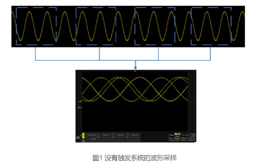
First of all, let's understand the trigger principle of the oscilloscope. As we all know, the oscilloscope trigger system and sampling system, is the two important components of the oscilloscope. Sampling system is responsible for digitizing the analog signal, but the signal is a source over, which part to take the display on the oscilloscope interface? If the oscilloscope does not have a trigger system, the use of every other time or randomly at a certain time will be sampled waveform superimposed, due to the uncertainty and irregularity of the sampling position, there will be a very confusing waveform display, on the oscilloscope screen looks like a waveform scrolling back and forth, as shown in the figure below this waveform.
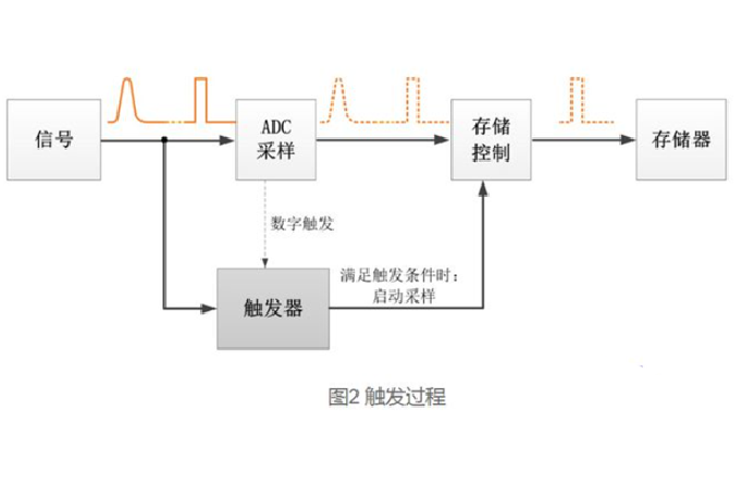
This depends on the trigger system to achieve. The principle of triggering is to monitor the signal flow all the time, and if the signal is found to meet the set triggering conditions, the trigger records the signal that meets the conditions and starts sampling; after the data is collected, the controller processes and displays the signal. The details are shown in Figure 2.
After understanding the Tektronix oscilloscope trigger principle, we move on to understand the three steps of oscilloscope stabilization trigger.
1、Auto determine the external appearance of the waveform
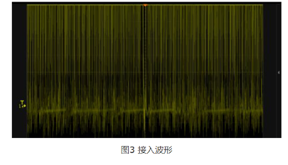
After connecting the signal into the oscilloscope we still don't know anything about it, so the 1st step is to use the Auto function first and capture the waveform. As in Figure 4, the Auto function will automatically determine the vertical gear according to the amplitude of the signal, include the waveform all into the display, and set the trigger threshold in the middle so that we have a first impression of the waveform: how large the waveform amplitude is.
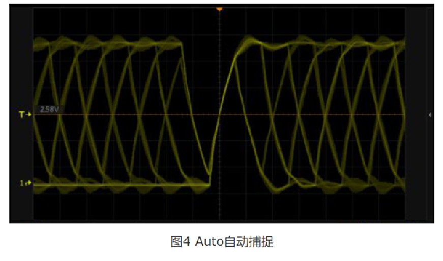
Now, what we can determine are: waveform amplitude, vertical gear.
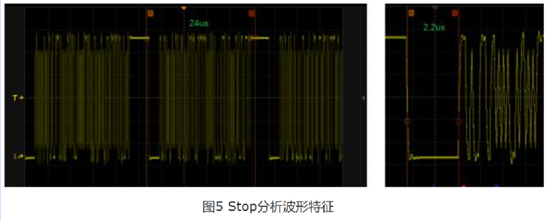
2、Stop to understand the waveform characteristics
After the amplitude characteristics of the vertical direction of the waveform are determined, next we need to determine the horizontal direction, that is, the time characteristics. For this we need to do two operations, 1) slightly increase the time base; 2) click [Run/Stop] in the oscilloscope panel to stop the waveform down.
3, adjust the threshold and trigger mode to accurately capture
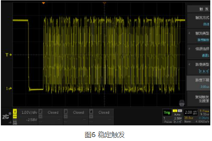
With the above 2 steps paving the way, the setting of step 3 becomes watertight. We choose pulse width trigger -> low level, because the burr interference of this waveform is not large, so the trigger threshold remains unchanged. Click [Run/Stop] in the oscilloscope panel to make the oscilloscope start acquiring again, as in Figure 6, the waveform has stabilized and can do further analysis.
Tektronix oscilloscope in the use of the first to get a stable trigger waveform, so as to ensure the reliability of the subsequent measurement, decoding and other advanced functions. Now the trigger function of the digital oscilloscope is becoming more and more powerful, from the conventional trigger, to the protocol trigger, and then to the template trigger, more and more powerful. Therefore, "trigger" is definitely called the concept of digital oscilloscope soul level, if there is no suitable trigger conditions, waveform observation can not begin to talk. Although many engineers are very familiar with the trigger function of the oscilloscope, but most are only aware of its surface do not know its inside. In the basic trigger settings, there are some small details can not be ignored, flexible mastery, the use of the oscilloscope is also very beneficial, then want to deep understanding of the oscilloscope trigger, you must be familiar with the oscilloscope trigger principle and trigger process, today Antai test to share with you the working principle of the oscilloscope and trigger process.
First of all, let's understand the trigger principle of the oscilloscope. As we all know, the oscilloscope trigger system and sampling system, is the two important components of the oscilloscope. Sampling system is responsible for digitizing the analog signal, but the signal is a source over, which part to take the display on the oscilloscope interface? If the oscilloscope does not have a trigger system, the use of every other time or randomly at a certain time will be sampled waveform superimposed, due to the uncertainty and irregularity of the sampling position, there will be a very confusing waveform display, on the oscilloscope screen looks like a waveform scrolling back and forth, as shown in the figure below this waveform.

This depends on the trigger system to achieve. The principle of triggering is to monitor the signal flow all the time, and if the signal is found to meet the set triggering conditions, the trigger records the signal that meets the conditions and starts sampling; after the data is collected, the controller processes and displays the signal. The details are shown in Figure 2.

After understanding the Tektronix oscilloscope trigger principle, we move on to understand the three steps of oscilloscope stabilization trigger.
1、Auto determine the external appearance of the waveform

After connecting the signal into the oscilloscope we still don't know anything about it, so the 1st step is to use the Auto function first and capture the waveform. As in Figure 4, the Auto function will automatically determine the vertical gear according to the amplitude of the signal, include the waveform all into the display, and set the trigger threshold in the middle so that we have a first impression of the waveform: how large the waveform amplitude is.

Now, what we can determine are: waveform amplitude, vertical gear.
2、Stop to understand the waveform characteristics
After the amplitude characteristics of the vertical direction of the waveform are determined, next we need to determine the horizontal direction, that is, the time characteristics. For this we need to do two operations, 1) slightly increase the time base; 2) click [Run/Stop] in the oscilloscope panel to stop the waveform down.

3, adjust the threshold and trigger mode to accurately capture
With the above 2 steps paving the way, the setting of step 3 becomes watertight. We choose pulse width trigger -> low level, because the burr interference of this waveform is not large, so the trigger threshold remains unchanged. Click [Run/Stop] in the oscilloscope panel to make the oscilloscope start acquiring again, as in Figure 6, the waveform has stabilized and can do further analysis.


