


Test methods for 400G optical modules? Eye diagram NRZ&PAM4


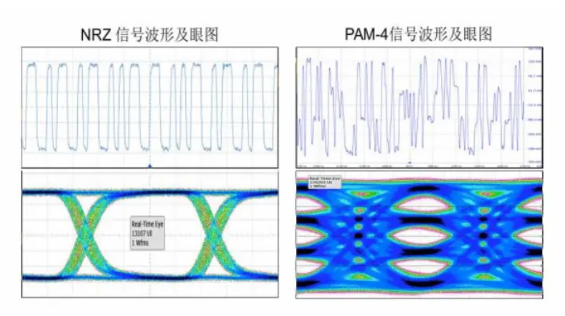
400G optical modules widely use PAM4 (4-level Pulse Amplitude Modulation) technology, which transmits signals through four different signal levels, with each symbol cycle representing 2 bits of logical information (0, 1, 2, 3). This technique allows signals to be transmitted at only half the symbol rate of NRZ signals, which greatly reduces the losses caused by the transmission channel. However, the signal-to-noise ratio can deteriorate much more than with NRZ signals, and there are significant differences in measurement methods. The figure below shows the waveform and eye diagram of a typical NRZ signal compared to a PAM4 signal.
The main high-speed interfaces of the 400G optical module include the electrical input interface, the optical output interface, the optical input interface, the electrical output interface, and other power and low-speed management interfaces. Therefore, electrical performance verification mainly involves optical port transmitter indicators, optical port receiver tolerances, electrical port transmitter indicators, electrical port receiver tolerances and system testing.
Transmitter Testing
Optical transmitter test method
Test environment: the optical module under test is inserted into the MCB fixture, powered on and configured for normal operation.
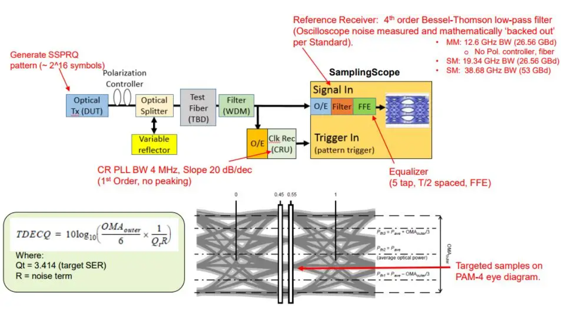
Test content: BER generates PAM4 electrical excitation signal to the optical module all the way to the electrical input, so that the optical module under test output SSPRQ optical signal, while input crosstalk signal. The output optical signal is recovered by the clock into the sampling oscilloscope for parameter testing.
Key indicators: TDECQ (Transmitter and dispersion eye closure for PAM4), a measure of the optical transmitter through the optical channel after the loss of PAM4 signal power margin.TDECQ reference test method is shown in the figure below:
Electrical transmitter test method
Test environment: the same as above.
Test content: BER generates PAM4 electrical excitation signal to optical module all the way to the electrical input, optical module adjacent to the electrical channel input PAM4 crosstalk signal. Output optical signal loop back to the optical receiver, and test its electrical channel output PRBS13Q signal parameters.
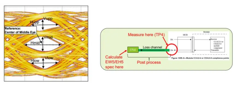
Key indicators: Eye Height and Eye Width, reflecting the quality of the electrical signal.
Receiver and BER Testing
Optical Receiver Test Methods
Test environment: A reference PAM4 signal source with jitter, noise, and inter-code interference injection sources, and a reference optical transmitter generating the desired optical pressure signal.
Test content: The optical pressure signal is characterized by the peripheral extinction ratio OER, the external optical modulation amplitude OOMA and the pressure eye diagram closure cost SECQ.
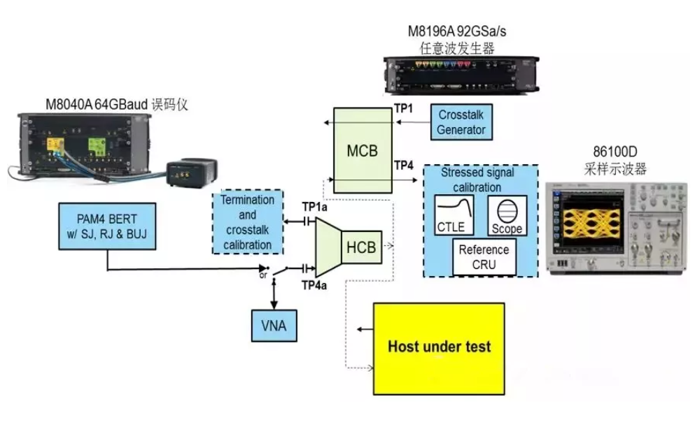
Electrical receiver test method
Test environment: Referring to an electrical transmitter (usually a code generator) as well as a jitter injection source, an inter-code interference source and a crosstalk source, the pressure electrical signal is fed into the MCB fixture.
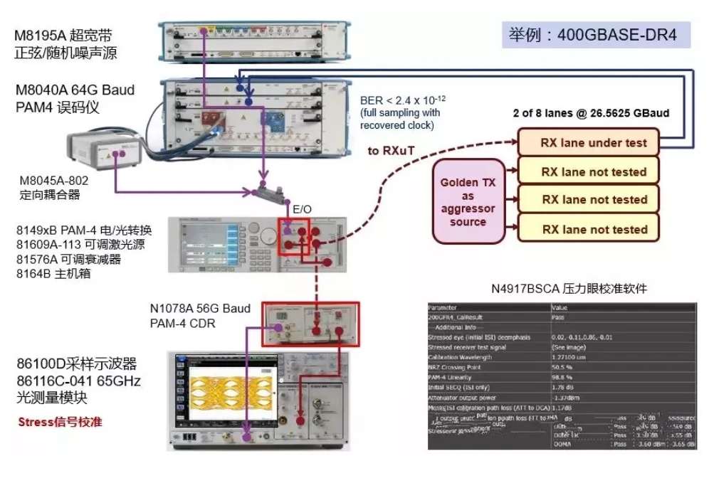
Test: The PAM4 electrostress signal is characterized by the frequency and amplitude of the eye diagram symmetrical template width ESMW, eye width EW, eye height EH and additional sinusoidal jitter SJ.
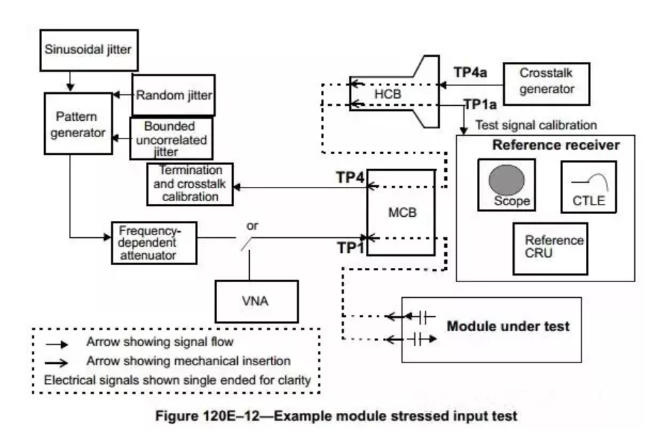
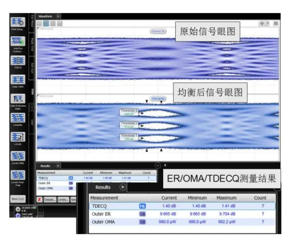
The figure below shows the actual test instrument used in the test.
System Test
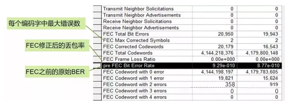
The system test is designed to verify the BER and error tolerance of the optical module under test when it works with the switch under real service traffic conditions. Due to the deterioration of the signal-to-noise ratio of PAM4 technology, the raw BER is difficult to reach the level of the traditional 2-level modulation, so the FEC technology is used to correct the random error bit to ensure that the packet loss rate is within the acceptable range. A typical system test environment is as follows:
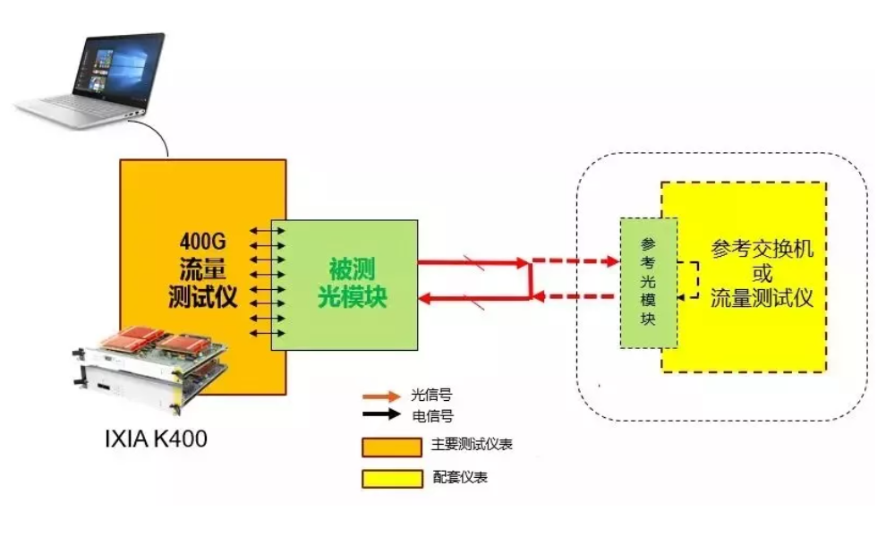
Tests include raw BER and FEC-corrected packet loss rate tests, as well as verification of system performance impacts under specific error symbols or frequency deviations.
The wide application of PAM4 and FEC technologies makes the testing and evaluation methods of 400G optical modules different from those of traditional 100G optical modules. In order to ensure good interconnection and reliable data transmission between devices, it is necessary to carry out detailed tests on its output quality, receive tolerance and BER under carrying real service data.
400G optical modules widely use PAM4 (4-level Pulse Amplitude Modulation) technology, which transmits signals through four different signal levels, with each symbol cycle representing 2 bits of logical information (0, 1, 2, 3). This technique allows signals to be transmitted at only half the symbol rate of NRZ signals, which greatly reduces the losses caused by the transmission channel. However, the signal-to-noise ratio can deteriorate much more than with NRZ signals, and there are significant differences in measurement methods. The figure below shows the waveform and eye diagram of a typical NRZ signal compared to a PAM4 signal.
The main high-speed interfaces of the 400G optical module include the electrical input interface, the optical output interface, the optical input interface, the electrical output interface, and other power and low-speed management interfaces. Therefore, electrical performance verification mainly involves optical port transmitter indicators, optical port receiver tolerances, electrical port transmitter indicators, electrical port receiver tolerances and system testing.
Transmitter Testing
Optical transmitter test method
Test environment: the optical module under test is inserted into the MCB fixture, powered on and configured for normal operation.
Test content: BER generates PAM4 electrical excitation signal to the optical module all the way to the electrical input, so that the optical module under test output SSPRQ optical signal, while input crosstalk signal. The output optical signal is recovered by the clock into the sampling oscilloscope for parameter testing.
Key indicators: TDECQ (Transmitter and dispersion eye closure for PAM4), a measure of the optical transmitter through the optical channel after the loss of PAM4 signal power margin.TDECQ reference test method is shown in the figure below:
Electrical transmitter test method
Test environment: the same as above.
Test content: BER generates PAM4 electrical excitation signal to optical module all the way to the electrical input, optical module adjacent to the electrical channel input PAM4 crosstalk signal. Output optical signal loop back to the optical receiver, and test its electrical channel output PRBS13Q signal parameters.
Key indicators: Eye Height and Eye Width, reflecting the quality of the electrical signal.
Receiver and BER Testing
Optical Receiver Test Methods
Test environment: A reference PAM4 signal source with jitter, noise, and inter-code interference injection sources, and a reference optical transmitter generating the desired optical pressure signal.
Test content: The optical pressure signal is characterized by the peripheral extinction ratio OER, the external optical modulation amplitude OOMA and the pressure eye diagram closure cost SECQ.
Electrical receiver test method
Test environment: Referring to an electrical transmitter (usually a code generator) as well as a jitter injection source, an inter-code interference source and a crosstalk source, the pressure electrical signal is fed into the MCB fixture.
Test: The PAM4 electrostress signal is characterized by the frequency and amplitude of the eye diagram symmetrical template width ESMW, eye width EW, eye height EH and additional sinusoidal jitter SJ.
The figure below shows the actual test instrument used in the test.
System Test
The system test is designed to verify the BER and error tolerance of the optical module under test when it works with the switch under real service traffic conditions. Due to the deterioration of the signal-to-noise ratio of PAM4 technology, the raw BER is difficult to reach the level of the traditional 2-level modulation, so the FEC technology is used to correct the random error bit to ensure that the packet loss rate is within the acceptable range. A typical system test environment is as follows:
Tests include raw BER and FEC-corrected packet loss rate tests, as well as verification of system performance impacts under specific error symbols or frequency deviations.
The wide application of PAM4 and FEC technologies makes the testing and evaluation methods of 400G optical modules different from those of traditional 100G optical modules. In order to ensure good interconnection and reliable data transmission between devices, it is necessary to carry out detailed tests on its output quality, receive tolerance and BER under carrying real service data.