


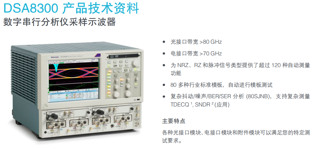
Tektronix DSA8300 TDR Impedance Test Operating Guide


How to perform a TDR impedance test using the DSA8300. The steps are as follows:
Select Channel: Click any one of the buttons C1, C2, C7, C8 (C1 is used as a demonstration below) to complete the basic TDR setup.
Select unit: Click the down arrow of Units on the panel to select the unit Ω.
Setup Parameters: After completing the above operations, click the Setup Dialog button on the panel or the Setup Dialogs shortcut icon at the bottom of the menu again to enter the advanced setup interface.
Advanced TDR Setup: In the advanced TDR setup interface, you can set the TDR step rate, reference source, and enable or disable the incident waveform display.
Probe Selection: Select the appropriate TDR probe according to your needs, such as P80318 true differential TDR probe and P8018 single-ended probe.
Measurement Preparation: Ensure all connections are correct and check the status of the device to confirm that it is properly installed and connected to the source.
Start Measurement: After completing all settings, click the Measurement button to start the test. The device will automatically perform the TDR impedance test and display the result.
With the above steps, you can use DSA8300 to perform efficient and accurate TDR impedance test. Please note that the recommendations in the relevant safety guidelines and manuals should be followed during operation to ensure the safety of the device and the operator.
What are the detailed operation steps of DSA8300 TDR impedance test?
Select the appropriate sampling module: According to the type and characteristics of the signals you want to measure, select an electrical interface module or an optical interface module and insert it into the corresponding slot of DSA8300.
Connect the test equipment: Make sure all the necessary connection cables and test equipment have been properly connected to DSA8300.
Setting Test Parameters: In the user interface of DSA8300, enter the corresponding test configuration menu to set the required test parameters, such as time reference, frequency range, etc. These parameters can be adjusted according to specific test requirements.
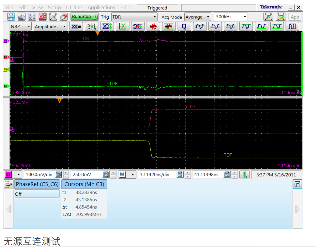
Perform data acquisition: Start the test and begin data acquisition. During the acquisition process, the DSA8300 will record the time domain data of the signal.
Analyse and Interpret Results: After data acquisition is complete, use the DSA8300's built-in software tools to analyse the acquired data. By plotting the data code curve, you can visualise the transmission characteristics of the signal, such as impedance changes.
Report generation: Finally, the test results are collated into a report and further analysed and presented as required.
What are the differences in performance parameters and application scenarios between DSA8300 TDR probes P80318 and P8018?
There are some differences in performance parameters and application scenarios between DSA8300 TDR probes P80318 and P8018.
Input impedance and frequency range:
The P80318 has an input impedance of 100 Ω and a frequency range of 18 GHz.
The P8018 has an input impedance of 50 Ω and a frequency range greater than 60 GHz.
Signal Type:
The P80318 is a true differential TDR probe for high fidelity impedance measurements on differential transmission lines.
The P8018 is a single-ended passive TDR probe for electrical sampling and high-speed electrical signal analysis in single-ended applications.
Application Scenarios:
The P80318 is suitable for differential transmission line impedance measurements where high fidelity is required, especially where the probe spacing needs to be adjusted to suit different line spacings and impedances.
The P8018 is more suitable for circuit board impedance characterisation and high-speed electrical signal analysis, especially when single-ended measurements are required.
Additional Features:
The P80318 includes two precision SMA cables with parallel control.
The P8018 provides a precision 20 GHz bandwidth SMA cable for high-performance electrical sampling TDR board impedance characterisation and high-speed electrical signal analysis.
The P80318 and P8018 probes each have their own features, and the choice depends on the specific needs of the application.
How to correctly select the reference source in DSA8300 TDR impedance test?
There are several key factors to consider when selecting a reference source in a DSA8300 TDR impedance test:
Output Impedance: The output impedance of a TDR is usually a 50 ohm standard resistor. Therefore, when selecting a reference source, it is important to ensure that its output impedance matches the output impedance of the TDR device to avoid signal reflection and loss.
Signal wavelength: TDR testing requires the use of high-speed signals and the signal wavelength should be much smaller than the size of the device to be tested. This means that the signal frequency of the reference source should be high enough to ensure that a short enough waveform can be captured for effective impedance analysis.
Signal Integrity: The DSA8300 has excellent bandwidth, signal fidelity and modular architecture for high performance TDR and interconnect analysis. Therefore, when selecting a reference source, its signal integrity and stability should be ensured to guarantee the accuracy of test results.
Therefore, when selecting a reference source, consider using a low-pass test mode for more information on impedance characteristics.
How do I set up and optimise the incident waveform display in a DSA8300 TDR impedance test?
Setting up and optimising the incident waveform display in a DSA8300 TDR impedance test can be done in the following steps:
Select the appropriate measurement parameters:
Ensure that you have selected the appropriate measurement parameters, such as bandwidth, rise time, etc. The DSA8300 supports bandwidths up to 50 GHz, with a suppression rise time of 15 ps and an incident rise time of 12 ps.
Configure the oscilloscope:
In the DSA8300 user interface, go to the ‘Oscilloscope’ settings section and adjust the vertical and horizontal resolution to ensure that the details of the incident waveform can be clearly captured.
Optimise the waveform display:
Use the ‘Waveform Capture’ function to record the incident waveform, the DSA8300 provides a variety of waveform capture options, you can choose the most suitable capture method according to your needs.
Use the ‘Pulse Restore’ function to calibrate the time axis to ensure the accuracy of the waveform data.
Reduce noise and jitter:
Reduce noise and jitter during testing with the ‘Jitter’ and ‘Noise’ processing functions to improve the clarity and accuracy of waveforms.
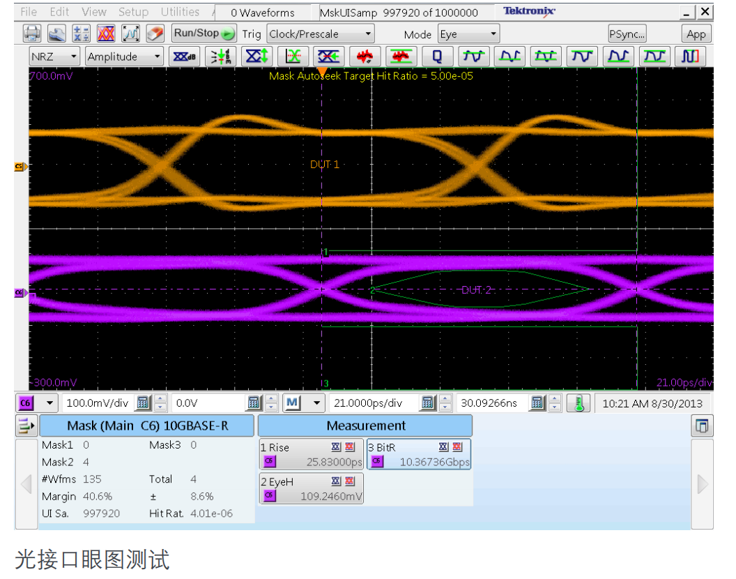
Use the Mask function:
Use the Mask function to further optimise the waveform display by setting different levels of masking to highlight important waveform features.
How to perform a TDR impedance test using the DSA8300. The steps are as follows:
Select Channel: Click any one of the buttons C1, C2, C7, C8 (C1 is used as a demonstration below) to complete the basic TDR setup.
Select unit: Click the down arrow of Units on the panel to select the unit Ω.
Setup Parameters: After completing the above operations, click the Setup Dialog button on the panel or the Setup Dialogs shortcut icon at the bottom of the menu again to enter the advanced setup interface.
Advanced TDR Setup: In the advanced TDR setup interface, you can set the TDR step rate, reference source, and enable or disable the incident waveform display.
Probe Selection: Select the appropriate TDR probe according to your needs, such as P80318 true differential TDR probe and P8018 single-ended probe.
Measurement Preparation: Ensure all connections are correct and check the status of the device to confirm that it is properly installed and connected to the source.
Start Measurement: After completing all settings, click the Measurement button to start the test. The device will automatically perform the TDR impedance test and display the result.
With the above steps, you can use DSA8300 to perform efficient and accurate TDR impedance test. Please note that the recommendations in the relevant safety guidelines and manuals should be followed during operation to ensure the safety of the device and the operator.
What are the detailed operation steps of DSA8300 TDR impedance test?
Select the appropriate sampling module: According to the type and characteristics of the signals you want to measure, select an electrical interface module or an optical interface module and insert it into the corresponding slot of DSA8300.
Connect the test equipment: Make sure all the necessary connection cables and test equipment have been properly connected to DSA8300.
Setting Test Parameters: In the user interface of DSA8300, enter the corresponding test configuration menu to set the required test parameters, such as time reference, frequency range, etc. These parameters can be adjusted according to specific test requirements.
Perform data acquisition: Start the test and begin data acquisition. During the acquisition process, the DSA8300 will record the time domain data of the signal.
Analyse and Interpret Results: After data acquisition is complete, use the DSA8300's built-in software tools to analyse the acquired data. By plotting the data code curve, you can visualise the transmission characteristics of the signal, such as impedance changes.
Report generation: Finally, the test results are collated into a report and further analysed and presented as required.
What are the differences in performance parameters and application scenarios between DSA8300 TDR probes P80318 and P8018?
There are some differences in performance parameters and application scenarios between DSA8300 TDR probes P80318 and P8018.
Input impedance and frequency range:
The P80318 has an input impedance of 100 Ω and a frequency range of 18 GHz.
The P8018 has an input impedance of 50 Ω and a frequency range greater than 60 GHz.
Signal Type:
The P80318 is a true differential TDR probe for high fidelity impedance measurements on differential transmission lines.
The P8018 is a single-ended passive TDR probe for electrical sampling and high-speed electrical signal analysis in single-ended applications.
Application Scenarios:
The P80318 is suitable for differential transmission line impedance measurements where high fidelity is required, especially where the probe spacing needs to be adjusted to suit different line spacings and impedances.
The P8018 is more suitable for circuit board impedance characterisation and high-speed electrical signal analysis, especially when single-ended measurements are required.
Additional Features:
The P80318 includes two precision SMA cables with parallel control.
The P8018 provides a precision 20 GHz bandwidth SMA cable for high-performance electrical sampling TDR board impedance characterisation and high-speed electrical signal analysis.
The P80318 and P8018 probes each have their own features, and the choice depends on the specific needs of the application.
How to correctly select the reference source in DSA8300 TDR impedance test?
There are several key factors to consider when selecting a reference source in a DSA8300 TDR impedance test:
Output Impedance: The output impedance of a TDR is usually a 50 ohm standard resistor. Therefore, when selecting a reference source, it is important to ensure that its output impedance matches the output impedance of the TDR device to avoid signal reflection and loss.
Signal wavelength: TDR testing requires the use of high-speed signals and the signal wavelength should be much smaller than the size of the device to be tested. This means that the signal frequency of the reference source should be high enough to ensure that a short enough waveform can be captured for effective impedance analysis.
Signal Integrity: The DSA8300 has excellent bandwidth, signal fidelity and modular architecture for high performance TDR and interconnect analysis. Therefore, when selecting a reference source, its signal integrity and stability should be ensured to guarantee the accuracy of test results.
Therefore, when selecting a reference source, consider using a low-pass test mode for more information on impedance characteristics.
How do I set up and optimise the incident waveform display in a DSA8300 TDR impedance test?
Setting up and optimising the incident waveform display in a DSA8300 TDR impedance test can be done in the following steps:
Select the appropriate measurement parameters:
Ensure that you have selected the appropriate measurement parameters, such as bandwidth, rise time, etc. The DSA8300 supports bandwidths up to 50 GHz, with a suppression rise time of 15 ps and an incident rise time of 12 ps.
Configure the oscilloscope:
In the DSA8300 user interface, go to the ‘Oscilloscope’ settings section and adjust the vertical and horizontal resolution to ensure that the details of the incident waveform can be clearly captured.
Optimise the waveform display:
Use the ‘Waveform Capture’ function to record the incident waveform, the DSA8300 provides a variety of waveform capture options, you can choose the most suitable capture method according to your needs.
Use the ‘Pulse Restore’ function to calibrate the time axis to ensure the accuracy of the waveform data.
Reduce noise and jitter:
Reduce noise and jitter during testing with the ‘Jitter’ and ‘Noise’ processing functions to improve the clarity and accuracy of waveforms.
Use the Mask function:
Use the Mask function to further optimise the waveform display by setting different levels of masking to highlight important waveform features.