


Keithley Model 2450 SourceMeter® Instrument-Operation in a Nutshell


The Model 2450 System SourceMeter® instrument is a precision, low-noise instrument that combines a stable DC power supply with a repeatable, high-impedance multimeter. The instrument is designed for intuitive setup and control, enhanced signal quality and extended ranges, and resistivity and resistance capabilities that are superior to similar products on the market. With both 6½-digit resolution and 0.012% basic accuracy, the 2450 provides 59 readings per second over the IEEE-488 bus. At 4½-bit accuracy, up to 1359 readings per second can be read into its internal buffer.
Powering the Instrument On or Off
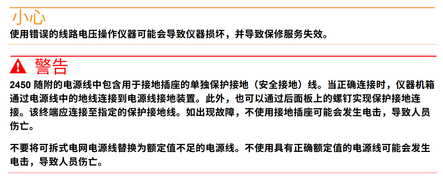
Follow the steps below to connect the 2450 to line power and turn the instrument on. 2450 operates from 100 V to 240 V at 50 Hz or 60 Hz. It automatically senses line voltage and frequency. Ensure that the operating voltage in your area meets the requirements. The 2450 must be switched on and allowed to warm up for at least 1 hour to reach rated accuracy.
To connect the power cord:
Make sure the front panel POWER switch is in the OFF (O) position.
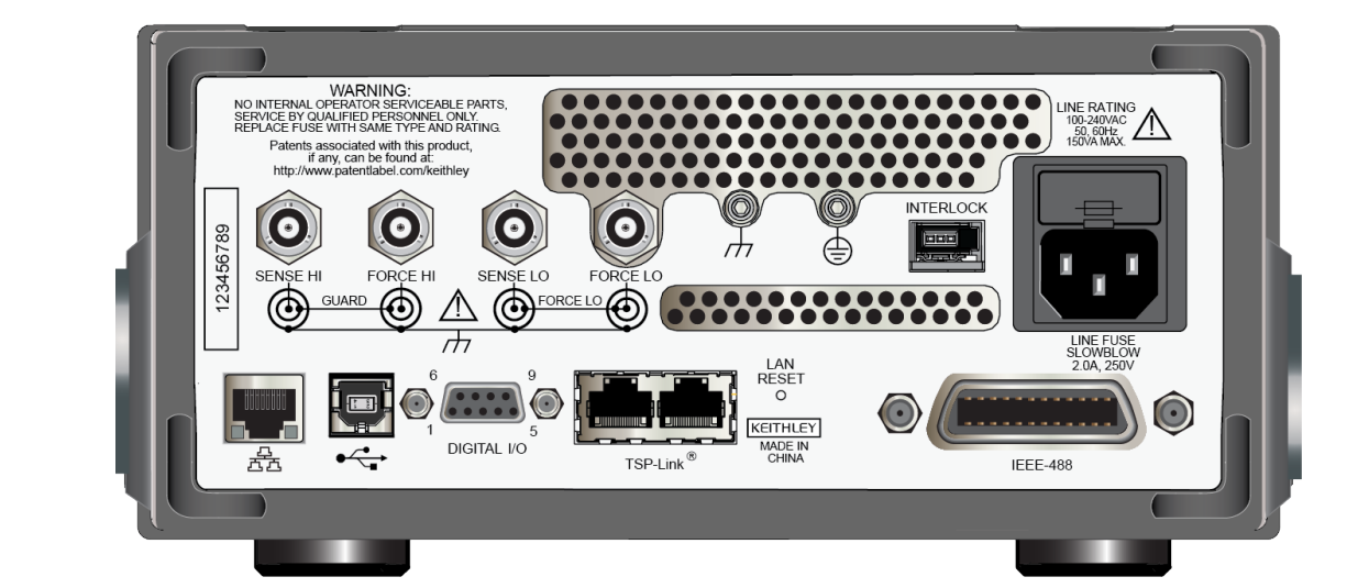
Connect the female end of the supplied power cord to an AC outlet on the rear panel.
Connect the male end of the power cord to a grounded AC outlet.
To turn the 2450 on or off:
Before turning on the instrument, disconnect any device under test (DUT) from the 2450.
To turn the instrument on, press the front panel POWER switch to the ON (|) position. The instrument displays a status bar at startup. The Home screen displays when power-up is complete.
To turn the instrument off, press the front panel POWER switch to the OFF (O) position.
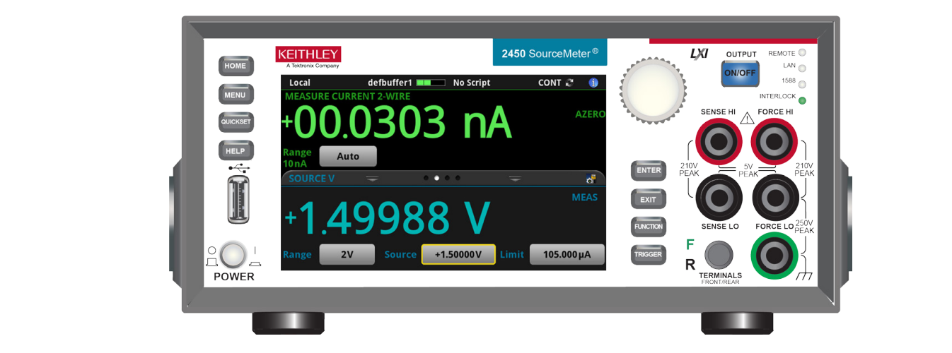
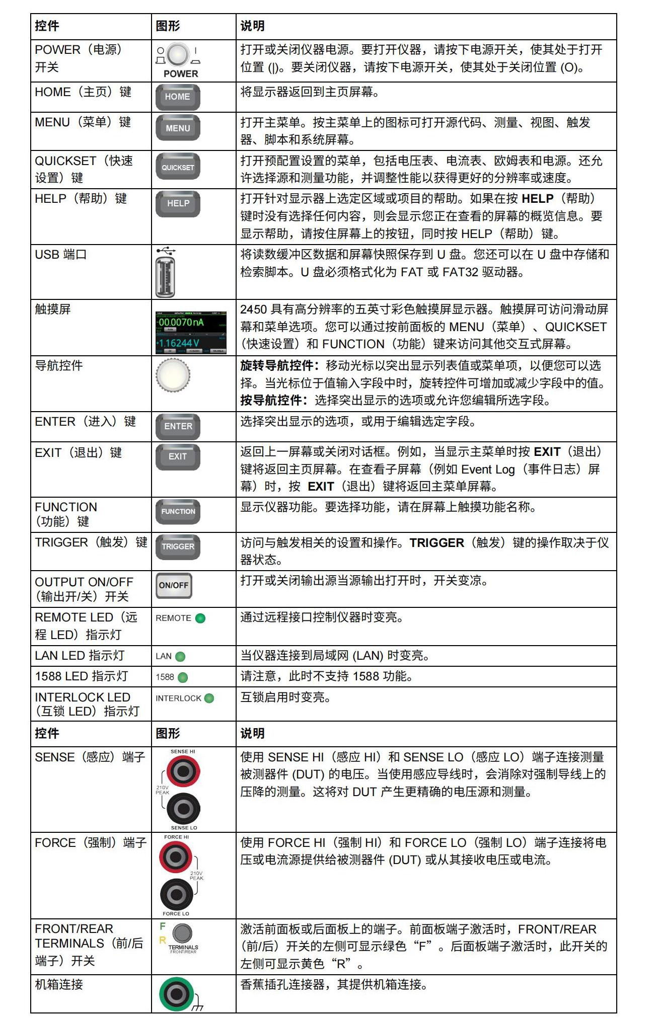
Front Panel Overview: The front panel of the 2450 is shown below. The controls on the front panel are described in the following figure.
Keithley 2450 GPIB Communications
The 2450 interface is IEEE Std 488.1 compliant and supports IEEE Std 488.2 common commands and state model topologies. Up to 15 devices can be connected to the GPIB interface, including controllers. The maximum cable length is the lesser of: - the number of devices multiplied by 2 metres (6.5 ft) - 20 metres (65.6 ft) Ignoring these limits may result in erratic bus operation.
Installing GPIB Driver Software
Check the documentation for your GPIB controller for information on where to obtain the driver.
Keithley Instruments also recommends that you check the GPIB controller's website for the latest version of the driver or software.
Be sure to install the driver before connecting the hardware. This prevents incorrect drivers from being associated with the hardware.
Install the GPIB card in the computer and refer to the documentation provided by the GPIB controller vendor for information on installing the GPIB controller.
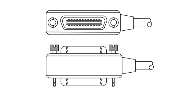
Connecting the GPIB Cable to the Instrument To connect the 2450 to the GPIB interface, use a cable with a standard GPIB connector, as shown below. To establish multiple parallel connections to an instrument, stack the connectors. Each connector has two screws to ensure a secure connection. The following figure shows a typical connection diagram for a test system with multiple instruments
The Model 2450 System SourceMeter® instrument is a precision, low-noise instrument that combines a stable DC power supply with a repeatable, high-impedance multimeter. The instrument is designed for intuitive setup and control, enhanced signal quality and extended ranges, and resistivity and resistance capabilities that are superior to similar products on the market. With both 6½-digit resolution and 0.012% basic accuracy, the 2450 provides 59 readings per second over the IEEE-488 bus. At 4½-bit accuracy, up to 1359 readings per second can be read into its internal buffer.
Powering the Instrument On or Off
Follow the steps below to connect the 2450 to line power and turn the instrument on. 2450 operates from 100 V to 240 V at 50 Hz or 60 Hz. It automatically senses line voltage and frequency. Ensure that the operating voltage in your area meets the requirements. The 2450 must be switched on and allowed to warm up for at least 1 hour to reach rated accuracy.
To connect the power cord:
Make sure the front panel POWER switch is in the OFF (O) position.
Connect the female end of the supplied power cord to an AC outlet on the rear panel.
Connect the male end of the power cord to a grounded AC outlet.
To turn the 2450 on or off:
Before turning on the instrument, disconnect any device under test (DUT) from the 2450.
To turn the instrument on, press the front panel POWER switch to the ON (|) position. The instrument displays a status bar at startup. The Home screen displays when power-up is complete.
To turn the instrument off, press the front panel POWER switch to the OFF (O) position.
Front Panel Overview: The front panel of the 2450 is shown below. The controls on the front panel are described in the following figure.
Keithley 2450 GPIB Communications
The 2450 interface is IEEE Std 488.1 compliant and supports IEEE Std 488.2 common commands and state model topologies. Up to 15 devices can be connected to the GPIB interface, including controllers. The maximum cable length is the lesser of: - the number of devices multiplied by 2 metres (6.5 ft) - 20 metres (65.6 ft) Ignoring these limits may result in erratic bus operation.
Installing GPIB Driver Software
Check the documentation for your GPIB controller for information on where to obtain the driver.
Keithley Instruments also recommends that you check the GPIB controller's website for the latest version of the driver or software.
Be sure to install the driver before connecting the hardware. This prevents incorrect drivers from being associated with the hardware.
Install the GPIB card in the computer and refer to the documentation provided by the GPIB controller vendor for information on installing the GPIB controller.
Connecting the GPIB Cable to the Instrument To connect the 2450 to the GPIB interface, use a cable with a standard GPIB connector, as shown below. To establish multiple parallel connections to an instrument, stack the connectors. Each connector has two screws to ensure a secure connection. The following figure shows a typical connection diagram for a test system with multiple instruments