


Instructions for connecting equipment related to pressure eye testing of optical modules


Pressure eye test, an important indicator for evaluating the performance of 25-28G optical receivers, is mainly to verify the degree of tolerance of the receiving end to poor signals.
The related equipments used here are: AXIe mainframe M9502A+M8195A AWG module+M9537A built-in PC controller, M9505A mainframe+M8046A high-performance BER+M8045A code generator, Remote Head M8057A, DCA-M N1092C,8164B lightwave mainframe system, which is integrated with the light sources such as 81608A+81942A Reference Receiver+81577A Attenuator. There are also some small parts such as combiner, directional coupler, several optical fibers, several adapters.
This article will specifically describe how to connect between each device interface test to build an optical receiver pressure eye test system.
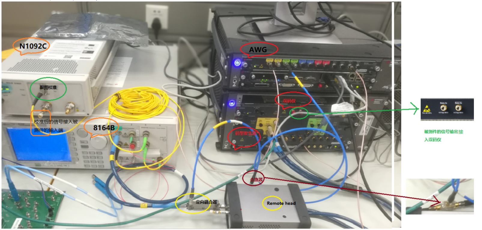
The connections for the physical diagram are as follows:
The connecting wires of the AWG output combiner are as short as possible to minimize loss.
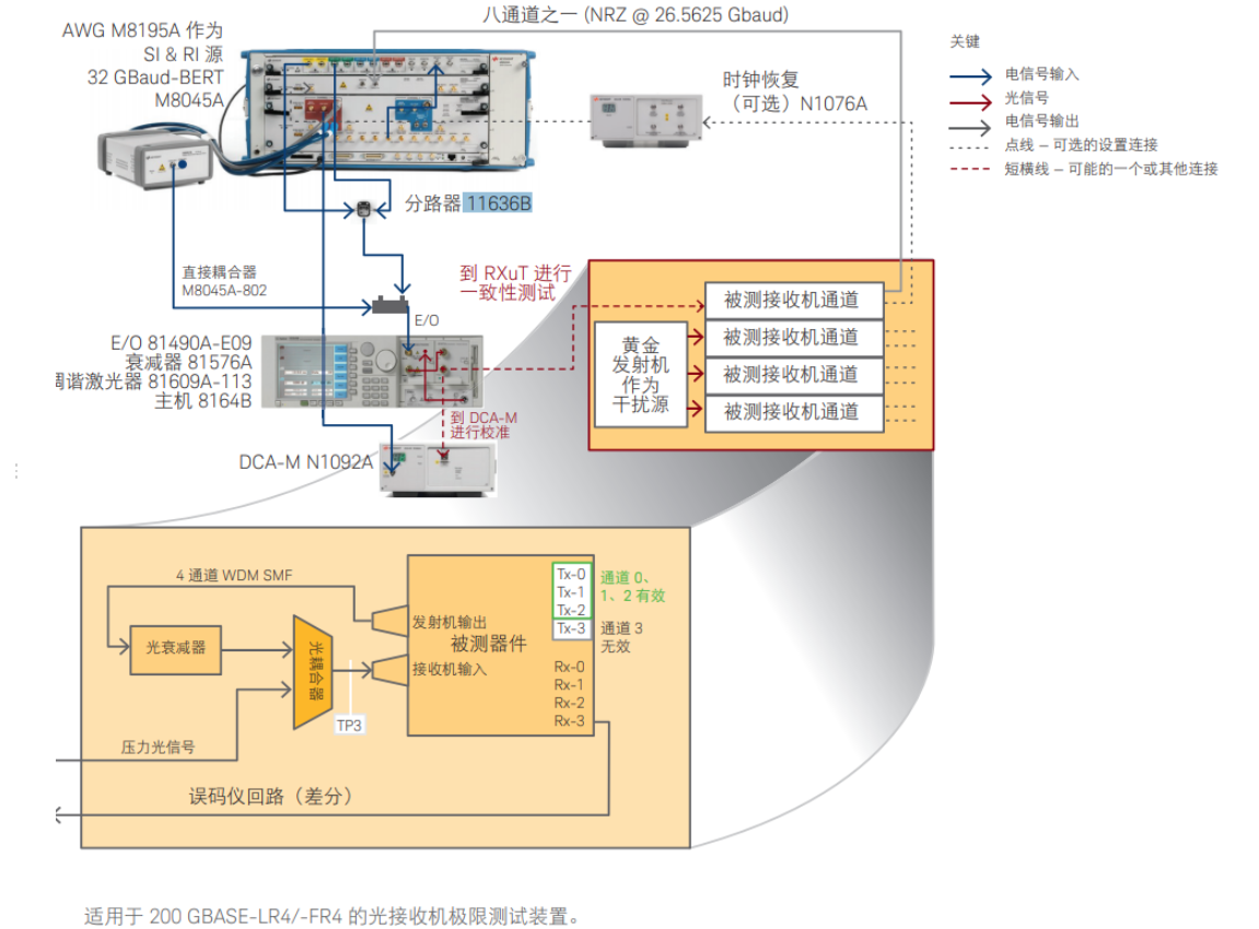
According to the 400G and 200G test standard 802.3bs, the tolerance test includes amplitude interference test and time delay interference test.
AWG M8195A: Generates amplitude interference, requiring two signals, one sinusoidal and one Gaussian.
Combiner (splitter): Combine the two signals used for interference at the AWG output.
Code Generator M8045A: generates code signals and time-delay interference.
BER Meter M8046A: Tests the BER.
DCA-M: Used for calibration of pressure eye diagrams prior to testing.
Reference Transmitter 81492A: Optoelectronic conversion unit to modulate electrical signals to a carrier light source
Light source 81608A: provides carrier signals in the corresponding bands
Bias preserving fiber: used to connect the tunable laser source to the reference transmitter
The role of the optical attenuator: used to adjust the size of the attenuation value, and thus change the amplitude of the signal, to do different amplitudes under the tolerance test.
Coupler: to couple the interfering signal with the code signal.
Remote head M8057A: extends the output of the code pattern generator.
PC Controller M9537A: Connects each test device via USB cable. The test software N4917BSCA can be installed in the PC controller to identify, calibrate and test all the instruments connected to the PC controller M9537A. In addition, the installed FlexDCA software will also calibrate the eye diagram for the signals connected to the DCA-M.
Clock Reference
Provided by the code generator M8045A.
Test Flow Connection Lines
AWG will output two interference signals, one way sine, one way Gaussian noise signal, through the combiner after the output signal, and the code pattern generator output code and jitter signals (through the remote head (Remote head) along the end of the output, the remote head (Remote head) another output port to do the termination, to prevent external signals crosstalk through the port into the other useful signals outlet), through the directional coupler coupling ), coupled through the directional coupler, access to the reference transmitter's electrical port, and then with the light source output to the reference transmitter of the light source carrier signal linear amplitude modulation, modulated signal input to the attenuator 81577A, the attenuator output signal and then access to the DCA-M, the eye diagram (to do the test link) to do the calibration. After the calibration passes, then the calibrated signal is input to the DUT, the output of the DUT, the output signal to the differential input of the BER M8046A, to do the BER test.
In this process, you need to do clock synchronization, code generator clock out to the BER clock in, from the BER clock out port output to the DCA-M clock in (eye calibration, test products will not use the DCA-M). The Trig out signal of the code generator can be set as another clock signal to be provided to the AWG M8195A, which constitutes the synchronization of the signal.
Note: To change the wavelength, you need to redo the calibration and test again.
Pressure eye test, an important indicator for evaluating the performance of 25-28G optical receivers, is mainly to verify the degree of tolerance of the receiving end to poor signals.
The related equipments used here are: AXIe mainframe M9502A+M8195A AWG module+M9537A built-in PC controller, M9505A mainframe+M8046A high-performance BER+M8045A code generator, Remote Head M8057A, DCA-M N1092C,8164B lightwave mainframe system, which is integrated with the light sources such as 81608A+81942A Reference Receiver+81577A Attenuator. There are also some small parts such as combiner, directional coupler, several optical fibers, several adapters.
This article will specifically describe how to connect between each device interface test to build an optical receiver pressure eye test system.
The connections for the physical diagram are as follows:
The connecting wires of the AWG output combiner are as short as possible to minimize loss.
According to the 400G and 200G test standard 802.3bs, the tolerance test includes amplitude interference test and time delay interference test.
AWG M8195A: Generates amplitude interference, requiring two signals, one sinusoidal and one Gaussian.
Combiner (splitter): Combine the two signals used for interference at the AWG output.
Code Generator M8045A: generates code signals and time-delay interference.
BER Meter M8046A: Tests the BER.
DCA-M: Used for calibration of pressure eye diagrams prior to testing.
Reference Transmitter 81492A: Optoelectronic conversion unit to modulate electrical signals to a carrier light source
Light source 81608A: provides carrier signals in the corresponding bands
Bias preserving fiber: used to connect the tunable laser source to the reference transmitter
The role of the optical attenuator: used to adjust the size of the attenuation value, and thus change the amplitude of the signal, to do different amplitudes under the tolerance test.
Coupler: to couple the interfering signal with the code signal.
Remote head M8057A: extends the output of the code pattern generator.
PC Controller M9537A: Connects each test device via USB cable. The test software N4917BSCA can be installed in the PC controller to identify, calibrate and test all the instruments connected to the PC controller M9537A. In addition, the installed FlexDCA software will also calibrate the eye diagram for the signals connected to the DCA-M.
Clock Reference
Provided by the code generator M8045A.
Test Flow Connection Lines
AWG will output two interference signals, one way sine, one way Gaussian noise signal, through the combiner after the output signal, and the code pattern generator output code and jitter signals (through the remote head (Remote head) along the end of the output, the remote head (Remote head) another output port to do the termination, to prevent external signals crosstalk through the port into the other useful signals outlet), through the directional coupler coupling ), coupled through the directional coupler, access to the reference transmitter's electrical port, and then with the light source output to the reference transmitter of the light source carrier signal linear amplitude modulation, modulated signal input to the attenuator 81577A, the attenuator output signal and then access to the DCA-M, the eye diagram (to do the test link) to do the calibration. After the calibration passes, then the calibrated signal is input to the DUT, the output of the DUT, the output signal to the differential input of the BER M8046A, to do the BER test.
In this process, you need to do clock synchronization, code generator clock out to the BER clock in, from the BER clock out port output to the DCA-M clock in (eye calibration, test products will not use the DCA-M). The Trig out signal of the code generator can be set as another clock signal to be provided to the AWG M8195A, which constitutes the synchronization of the signal.
Note: To change the wavelength, you need to redo the calibration and test again.