


400G optical module main test items


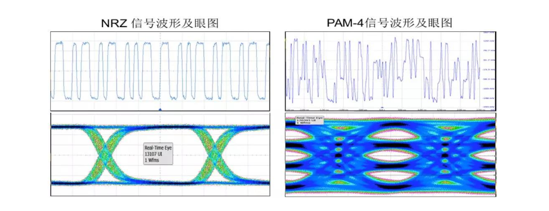
400G optical modules commonly use the PAM4 (4-level Pulse Amplitude Modulation: 4-level pulse amplitude modulation) signal modulation technology, that is, the use of four different signal levels for signal transmission, each symbol cycle can represent 2 bits of logical information (0, 1, 2, 3).
Therefore, to achieve the same signal transmission capability, the symbol rate of the PAM4 signal only needs to reach half of that of the NRZ signal, and the loss caused by the transmission channel is greatly reduced, but the price paid is that the signal-to-noise ratio will be much worse than that of the NRZ signal, and the measurement method will be more different. The following figure shows the waveform and eye diagram of a typical NRZ signal compared with a PAM4 signal.
For 400G optical module, its main high-speed interfaces include electrical input interface, optical output interface, optical input interface, electrical output interface, and other power and low-speed management interfaces. Therefore, for the electrical performance verification of 400G optical modules, the main test items are divided into optical port transmitter index, optical port receiver tolerance, electrical port transmitter index, electrical port receiver tolerance, and system test.
Transmitter test: Optical transmitter and electrical transmitter electrical characteristics test environment is as follows.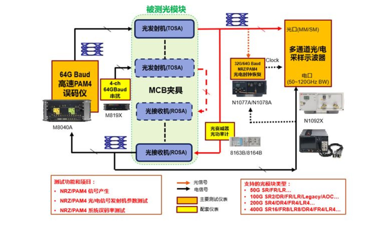
The measurement items of the transmitter are further divided into the measurement items of the optical transmitter and the measurement items of the electric transmitter, which are mainly used to verify the quality of the output signals of the optical and electric ports.
Optical transmitter test method
Mainly used to verify the quality of the optical signal from the optical module under test. The test method is as follows: the optical module under test is inserted into the MCB fixture, powered on and configured to work normally; the BER generates a PAM4 electrical excitation signal to the optical module all the way to the electrical input, making the optical module under test output the optical signal of SSPRQ, and the crosstalk signal of PAM4 is input on the adjacent electrical channel of the module. The output optical signal is recovered by the clock into the sampling oscilloscope for optical transmitter parameter testing. Replace the other channels in turn to measure all channels optical transmitter indicators.
TDECQ (Transmitter and dispersion eye closure for PAM4), the cost of transmitter dispersion eye diagram closure, is a measure of the loss of PAM4 signal power margin after a typical optical channel of the optical transmitter. The lasers normally used for optical signal transmission have a certain spectral width, and after a certain distance of transmission, the dispersion effect causes a change in the transmission delay of the different wavelength components of the signal. These signals with different transmission delays are superimposed at the receiving end to cause deterioration of the signal quality, which leads to a decrease in sensitivity at the receiving end.
In the 10G Ethernet IEEE 802.3ae standard, this metric is defined as TDP (Transmitter and Dispersion Penalty); in the 100G Ethernet IEEE 802.3bm standard, this metric is defined as TDEC (Transmitter and Dispersion Eye Closure); and in the IEEE 802.3bs standard for 200G/400G Ethernet, this metric is TDECQ (Transmitter and dispersion eye closure for PAM4).
TDECQ is usually expressed in dB, and for PAM4 signals, the smaller the TDECQ value, the smaller the power margin loss of the signal with respect to the ideal signal, or the longer distance it can be transmitted in the fiber. According to the definition in 802.3bs, the reference test method for TDECQ is shown in the following figure:
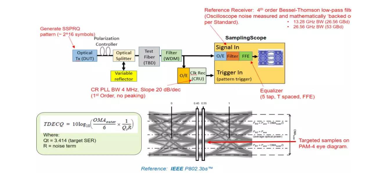
In the test, the optical signal of the SSPRQ code type is generated by the device under test and then transmitted through the test fiber. The signal under test is transmitted through the optical fiber and then enters the sampling oscilloscope for measurement. The sampling oscilloscope performs clock recovery through a CRU (Clock Data Recovery) circuit that meets the specifications on the one hand, and samples the optical signal under test through a reference filter on the other. The sampled waveform is subjected to 5th-order FFE signal equalization, and then the CRU recovery clock is used as the reference to form the PAM4 signal eye diagram.
After the eye diagram is formed, the TDECQ value is calculated based on the signal eye diagram's optical modulation amplitude (OMA), signal amplitude noise (R), and the extrapolation factor (Qt) corresponding to the BER requirement according to the formula.
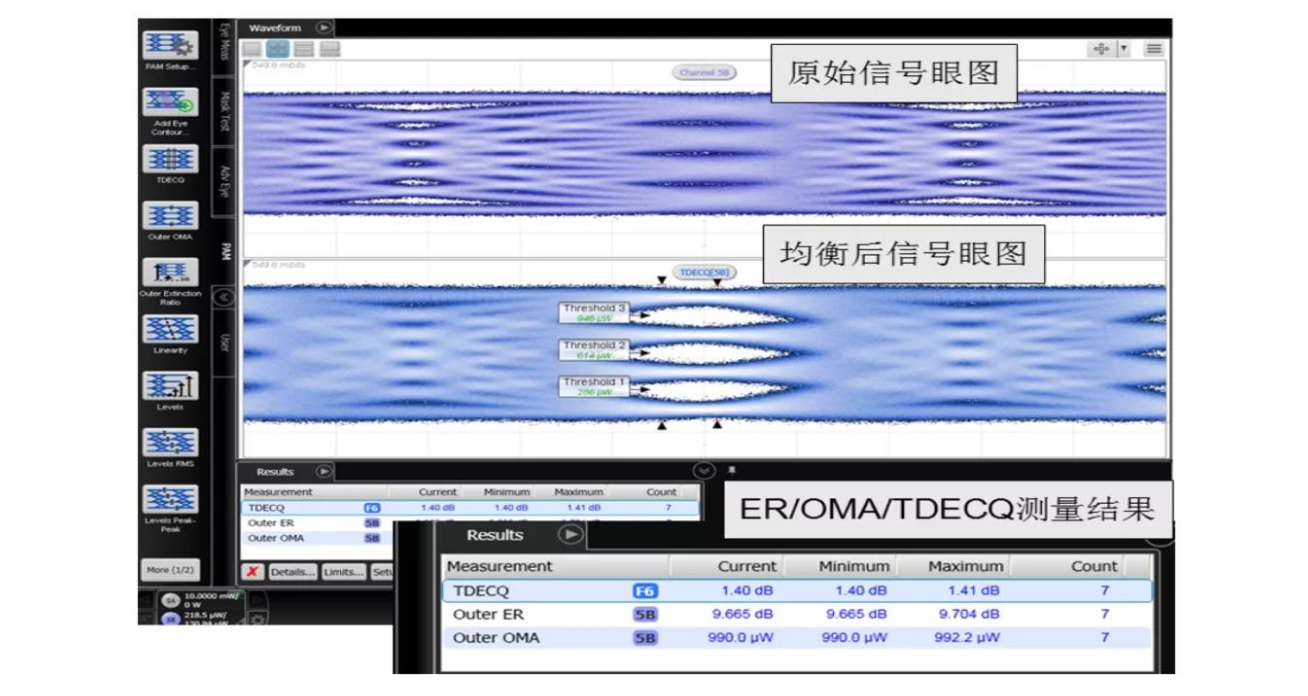
The following figure shows an example of testing the parameters of the equalized optical signal in a sampling oscilloscope for OMA, ER, TDECQ, and other parameters. We can see that although the definition of many measurement parameters is very tedious, but based on the PAM4 measurement option in the oscilloscope, the user does not need tedious operation, you can quickly get the required measurement results.
Electric transmitter test method
It is mainly used to verify the quality of the electrical port output of the optical module under test. The test method is as follows: the optical module under test is inserted into the MCB fixture, powered on and configured for normal operation; the BER generates a PAM4 electrical excitation signal to the optical module all the way to the electrical input, and the crosstalk signal of PAM4 is input on the adjacent electrical channel of the optical module. Output optical signal loop back to the optical receiver, and test its electrical channel output PRBS13Q signal parameters.
Eye Height (Eye Height) and Eye Width (Eye Width) are important parameters for testing the electrical signal quality of the 400G optical module. In the IEEE 802.3bs specification, the PAM4 code type of PRBS13Q is used to define the eye diagram test. The signal output from the point under test is superimposed after the reference equalizer and clock recovery to form the eye diagram. Therefore, an oscilloscope with the right bandwidth, the right equalizer and reliable clock recovery are essential for eye diagram testing of PAM4 signals. For the Module output test, it is also necessary to simulate the impact of signal loss on the signal through the internal alignment of the Host, so the test oscilloscope also needs to be overlaid on the captured signal about 6.4dB of transmission channel loss.
Since the PAM4 signal will form a 3-layer eye diagram, so each layer of the eye diagram should be measured separately. In the IEEE 802.3bs specification, the center of the middle layer eye diagram is defined as the reference point to calculate the eye height and eye width. The equivalent eye height and eye width are calculated based on the noise and jitter probability distribution of the signal, which is a very complicated calculation process and is not discussed here.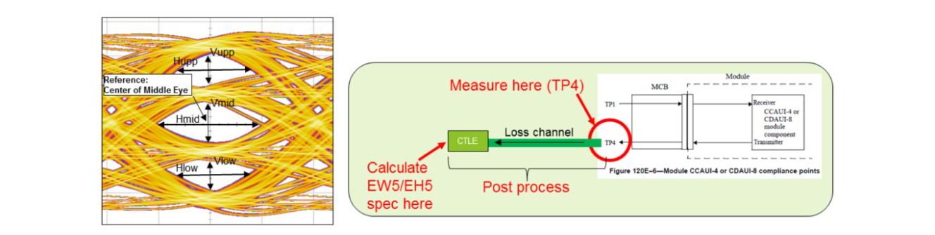
Receiver and BER testing
The transmitter test program is mainly used to ensure the quality of the optical and electrical port output signals of the optical module. Strictly speaking, it is also necessary to verify the ability of the optical and electrical ports of the optical module to receive signals.
The optical signal received by the optical module is usually transmitted over a long distance by optical fiber, and the received optical signal may have various jitter and noise superimposed on it, so the optical receiver test can be used to verify the tolerance ability of the optical module under test for the harsh optical signal.
At the same time, the optical module needs to receive the electrical signal sent from the switch or server from the electrical port and convert it into an optical signal to send out. As the electrical signal is transmitted through the PCB and connector, it will produce large loss and emission, so the electrical receiver test program can verify the tolerance ability of the optical module under test for the harsh electrical signal.
Optical receiver test method
The IEEE 802.3bs specification for the optical receiver pressure tolerance test method is described as follows: through the reference PAM4 signal source with jitter, noise, inter-code interference injection source, and the reference optical transmitter to generate the required optical pressure signal.
The optical pressure signal is characterized by the peripheral extinction ratio OER, the external optical modulation amplitude OOMA, and the pressure eye diagram closure cost SECQ. The PAM4 optical pressure signal is first calibrated by a reference optical receiver to ensure that its parameters meet the specification requirements. This receiver contains an ideal 4th order Bessel-Thomson low-pass filter that meets specification requirements, a specification-required FIR equalizer, and a clock recovery function.
The calibrated optical pressure signal is fed into one channel of the receiver under test, and the rest of the channels of the receiver under test are fed with the normal communication optical signal. Finally, the optical module under test loops back the electrical signal to the BER detection port of the BER meter, or through the internal BER statistics function of the receiver for BER and pressure sensitivity tests. The following figure shows the block diagram of the optical pressure eye diagram test of 400G-DR4 optical module, and the corresponding test instrument for each part.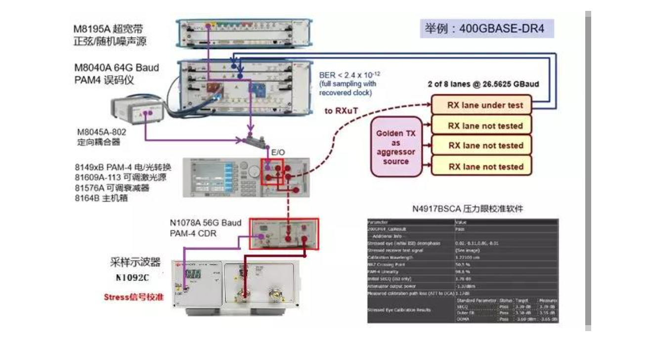
Electrical Receiver Test Method
The IEEE 802.3bs specification describes the pressure tolerance test method for the electrical input port of an optical module as follows: The pressure electrical signal is fed into the MCB fixture through a reference electrical transmitter (usually a code generator) as well as a jitter injection source, an inter-code interference source and a crosstalk source. The reference receiver (usually an oscilloscope) is then connected to the MCB fixture through the HCB fixture to calibrate the pressure electrical signal.
The reference receiver contains an ideal 4th-order Bessel-Thomson filter that meets the specification requirements, a CTLE equalizer that meets the specification requirements, and a clock recovery function. the PAM4 electrical pressure signal is characterized by the frequency and amplitude of the eye-diagram symmetric template width ESMW, eye width EW, eye height EH, and additional sinusoidal jitter SJ. The calibrated electrical pressure signal is connected to the measured channel of the electrical input port of the module under test and is tested for BER and receive tolerance by the FEC BER detection function inside the module or loopback output to an external BER analyzer for analysis.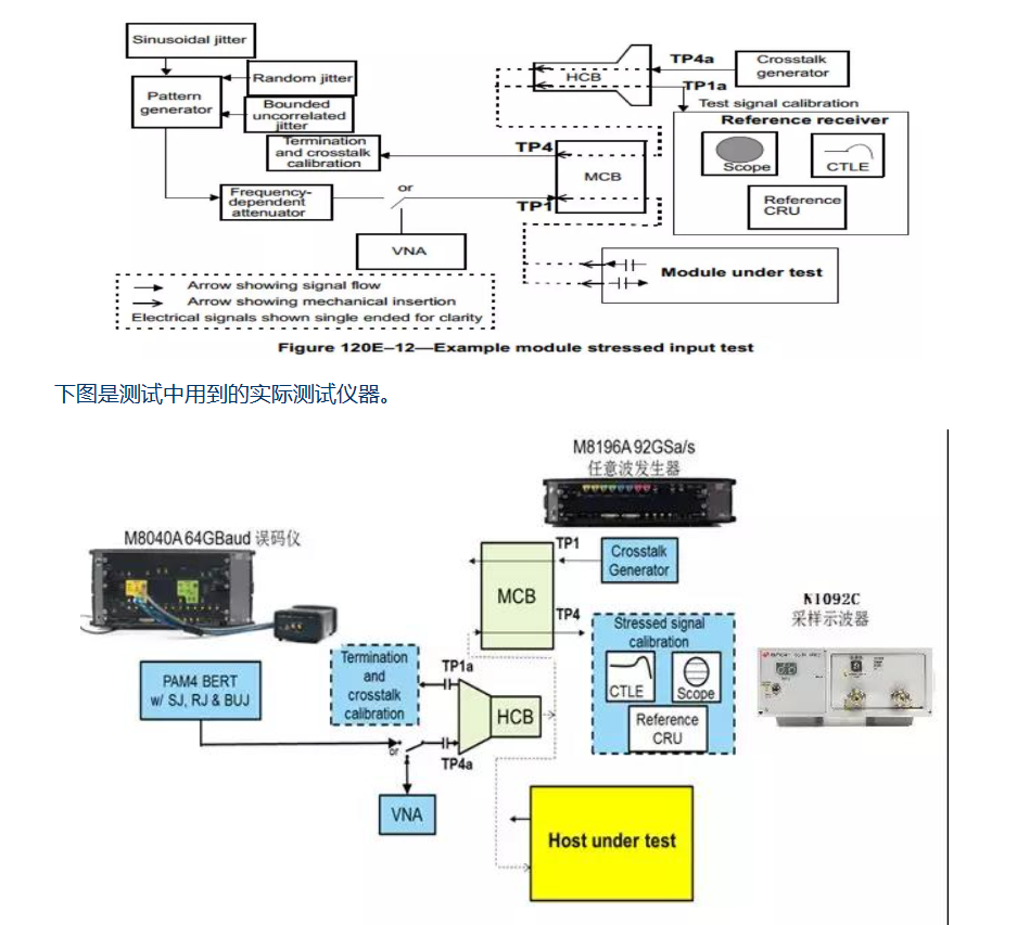
System Test
The main purpose of the system test is to verify the optical module under test with the work of the switch, the BER and error tolerance in the case of real service traffic. 400G optical modules generally use PAM4 (4 level modulation) technology, although reducing the bandwidth required for high-speed signal transmission, but due to the deterioration of the signal-to-noise ratio, making it difficult to achieve the original BER of the traditional 2 level modulation when the 1e-12 level, so its original BER requirements are relatively low, such as the IEEE 802.3bs for optical port BER requirements of just 2.4e-4.
Many communication processes cannot work properly with such a high BER, so FEC (Forward Error Correction) technology is commonly used. fec is a redundant checksum bit inserted in the data block, which can correct the randomly generated error bits, thus ensuring that the final packet loss rate is within an acceptable range (<6.2e-11).
Therefore, the system test needs to test both the original BER of the optical module and the packet loss rate after FEC correction, and verify whether the system performance is affected in the event of a given random error symbol or frequency deviation. A typical system test environment is as follows:
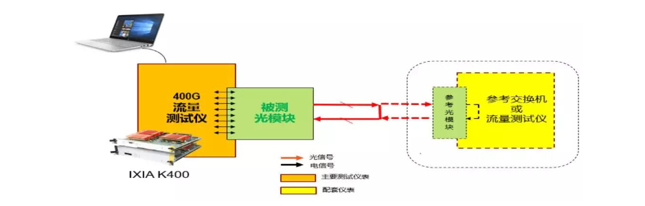
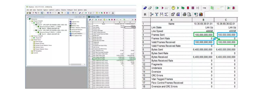
The test method is as follows: send 64-byte-length continuous data frames on the data traffic tester, and the BER value before FEC correction should be less than 2.4e-4; run the Ethernet traffic test software on the traffic tester and send 64-byte-length, 100% line rate data frames, and after accumulating at least 1e+12 data frames, the Frame Loss Ratio value of the read port should be less than 6.2e-11; perform BER injection of single or multiple (<15) after FEC on the traffic tester and verify that the BER after FEC meets the specification requirements of 802.3bs; adjust the rate by 100ppm on the traffic tester and verify that the BER and BER meet the specification requirements of 802.3bs.
The following figure shows an example of BER before FEC correction and packet loss rate test after FEC correction.
400G optical modules commonly use the PAM4 (4-level Pulse Amplitude Modulation: 4-level pulse amplitude modulation) signal modulation technology, that is, the use of four different signal levels for signal transmission, each symbol cycle can represent 2 bits of logical information (0, 1, 2, 3).
Therefore, to achieve the same signal transmission capability, the symbol rate of the PAM4 signal only needs to reach half of that of the NRZ signal, and the loss caused by the transmission channel is greatly reduced, but the price paid is that the signal-to-noise ratio will be much worse than that of the NRZ signal, and the measurement method will be more different. The following figure shows the waveform and eye diagram of a typical NRZ signal compared with a PAM4 signal.
For 400G optical module, its main high-speed interfaces include electrical input interface, optical output interface, optical input interface, electrical output interface, and other power and low-speed management interfaces. Therefore, for the electrical performance verification of 400G optical modules, the main test items are divided into optical port transmitter index, optical port receiver tolerance, electrical port transmitter index, electrical port receiver tolerance, and system test.
Transmitter test: Optical transmitter and electrical transmitter electrical characteristics test environment is as follows.
The measurement items of the transmitter are further divided into the measurement items of the optical transmitter and the measurement items of the electric transmitter, which are mainly used to verify the quality of the output signals of the optical and electric ports.
Optical transmitter test method
Mainly used to verify the quality of the optical signal from the optical module under test. The test method is as follows: the optical module under test is inserted into the MCB fixture, powered on and configured to work normally; the BER generates a PAM4 electrical excitation signal to the optical module all the way to the electrical input, making the optical module under test output the optical signal of SSPRQ, and the crosstalk signal of PAM4 is input on the adjacent electrical channel of the module. The output optical signal is recovered by the clock into the sampling oscilloscope for optical transmitter parameter testing. Replace the other channels in turn to measure all channels optical transmitter indicators.
TDECQ (Transmitter and dispersion eye closure for PAM4), the cost of transmitter dispersion eye diagram closure, is a measure of the loss of PAM4 signal power margin after a typical optical channel of the optical transmitter. The lasers normally used for optical signal transmission have a certain spectral width, and after a certain distance of transmission, the dispersion effect causes a change in the transmission delay of the different wavelength components of the signal. These signals with different transmission delays are superimposed at the receiving end to cause deterioration of the signal quality, which leads to a decrease in sensitivity at the receiving end.
In the 10G Ethernet IEEE 802.3ae standard, this metric is defined as TDP (Transmitter and Dispersion Penalty); in the 100G Ethernet IEEE 802.3bm standard, this metric is defined as TDEC (Transmitter and Dispersion Eye Closure); and in the IEEE 802.3bs standard for 200G/400G Ethernet, this metric is TDECQ (Transmitter and dispersion eye closure for PAM4).
TDECQ is usually expressed in dB, and for PAM4 signals, the smaller the TDECQ value, the smaller the power margin loss of the signal with respect to the ideal signal, or the longer distance it can be transmitted in the fiber. According to the definition in 802.3bs, the reference test method for TDECQ is shown in the following figure:
In the test, the optical signal of the SSPRQ code type is generated by the device under test and then transmitted through the test fiber. The signal under test is transmitted through the optical fiber and then enters the sampling oscilloscope for measurement. The sampling oscilloscope performs clock recovery through a CRU (Clock Data Recovery) circuit that meets the specifications on the one hand, and samples the optical signal under test through a reference filter on the other. The sampled waveform is subjected to 5th-order FFE signal equalization, and then the CRU recovery clock is used as the reference to form the PAM4 signal eye diagram.
After the eye diagram is formed, the TDECQ value is calculated based on the signal eye diagram's optical modulation amplitude (OMA), signal amplitude noise (R), and the extrapolation factor (Qt) corresponding to the BER requirement according to the formula.
The following figure shows an example of testing the parameters of the equalized optical signal in a sampling oscilloscope for OMA, ER, TDECQ, and other parameters. We can see that although the definition of many measurement parameters is very tedious, but based on the PAM4 measurement option in the oscilloscope, the user does not need tedious operation, you can quickly get the required measurement results.
Electric transmitter test method
It is mainly used to verify the quality of the electrical port output of the optical module under test. The test method is as follows: the optical module under test is inserted into the MCB fixture, powered on and configured for normal operation; the BER generates a PAM4 electrical excitation signal to the optical module all the way to the electrical input, and the crosstalk signal of PAM4 is input on the adjacent electrical channel of the optical module. Output optical signal loop back to the optical receiver, and test its electrical channel output PRBS13Q signal parameters.
Eye Height (Eye Height) and Eye Width (Eye Width) are important parameters for testing the electrical signal quality of the 400G optical module. In the IEEE 802.3bs specification, the PAM4 code type of PRBS13Q is used to define the eye diagram test. The signal output from the point under test is superimposed after the reference equalizer and clock recovery to form the eye diagram. Therefore, an oscilloscope with the right bandwidth, the right equalizer and reliable clock recovery are essential for eye diagram testing of PAM4 signals. For the Module output test, it is also necessary to simulate the impact of signal loss on the signal through the internal alignment of the Host, so the test oscilloscope also needs to be overlaid on the captured signal about 6.4dB of transmission channel loss.
Since the PAM4 signal will form a 3-layer eye diagram, so each layer of the eye diagram should be measured separately. In the IEEE 802.3bs specification, the center of the middle layer eye diagram is defined as the reference point to calculate the eye height and eye width. The equivalent eye height and eye width are calculated based on the noise and jitter probability distribution of the signal, which is a very complicated calculation process and is not discussed here.
Receiver and BER testing
The transmitter test program is mainly used to ensure the quality of the optical and electrical port output signals of the optical module. Strictly speaking, it is also necessary to verify the ability of the optical and electrical ports of the optical module to receive signals.
The optical signal received by the optical module is usually transmitted over a long distance by optical fiber, and the received optical signal may have various jitter and noise superimposed on it, so the optical receiver test can be used to verify the tolerance ability of the optical module under test for the harsh optical signal.
At the same time, the optical module needs to receive the electrical signal sent from the switch or server from the electrical port and convert it into an optical signal to send out. As the electrical signal is transmitted through the PCB and connector, it will produce large loss and emission, so the electrical receiver test program can verify the tolerance ability of the optical module under test for the harsh electrical signal.
Optical receiver test method
The IEEE 802.3bs specification for the optical receiver pressure tolerance test method is described as follows: through the reference PAM4 signal source with jitter, noise, inter-code interference injection source, and the reference optical transmitter to generate the required optical pressure signal.
The optical pressure signal is characterized by the peripheral extinction ratio OER, the external optical modulation amplitude OOMA, and the pressure eye diagram closure cost SECQ. The PAM4 optical pressure signal is first calibrated by a reference optical receiver to ensure that its parameters meet the specification requirements. This receiver contains an ideal 4th order Bessel-Thomson low-pass filter that meets specification requirements, a specification-required FIR equalizer, and a clock recovery function.
The calibrated optical pressure signal is fed into one channel of the receiver under test, and the rest of the channels of the receiver under test are fed with the normal communication optical signal. Finally, the optical module under test loops back the electrical signal to the BER detection port of the BER meter, or through the internal BER statistics function of the receiver for BER and pressure sensitivity tests. The following figure shows the block diagram of the optical pressure eye diagram test of 400G-DR4 optical module, and the corresponding test instrument for each part.
Electrical Receiver Test Method
The IEEE 802.3bs specification describes the pressure tolerance test method for the electrical input port of an optical module as follows: The pressure electrical signal is fed into the MCB fixture through a reference electrical transmitter (usually a code generator) as well as a jitter injection source, an inter-code interference source and a crosstalk source. The reference receiver (usually an oscilloscope) is then connected to the MCB fixture through the HCB fixture to calibrate the pressure electrical signal.
The reference receiver contains an ideal 4th-order Bessel-Thomson filter that meets the specification requirements, a CTLE equalizer that meets the specification requirements, and a clock recovery function. the PAM4 electrical pressure signal is characterized by the frequency and amplitude of the eye-diagram symmetric template width ESMW, eye width EW, eye height EH, and additional sinusoidal jitter SJ. The calibrated electrical pressure signal is connected to the measured channel of the electrical input port of the module under test and is tested for BER and receive tolerance by the FEC BER detection function inside the module or loopback output to an external BER analyzer for analysis.
System Test
The main purpose of the system test is to verify the optical module under test with the work of the switch, the BER and error tolerance in the case of real service traffic. 400G optical modules generally use PAM4 (4 level modulation) technology, although reducing the bandwidth required for high-speed signal transmission, but due to the deterioration of the signal-to-noise ratio, making it difficult to achieve the original BER of the traditional 2 level modulation when the 1e-12 level, so its original BER requirements are relatively low, such as the IEEE 802.3bs for optical port BER requirements of just 2.4e-4.
Many communication processes cannot work properly with such a high BER, so FEC (Forward Error Correction) technology is commonly used. fec is a redundant checksum bit inserted in the data block, which can correct the randomly generated error bits, thus ensuring that the final packet loss rate is within an acceptable range (<6.2e-11).
Therefore, the system test needs to test both the original BER of the optical module and the packet loss rate after FEC correction, and verify whether the system performance is affected in the event of a given random error symbol or frequency deviation. A typical system test environment is as follows:
The test method is as follows: send 64-byte-length continuous data frames on the data traffic tester, and the BER value before FEC correction should be less than 2.4e-4; run the Ethernet traffic test software on the traffic tester and send 64-byte-length, 100% line rate data frames, and after accumulating at least 1e+12 data frames, the Frame Loss Ratio value of the read port should be less than 6.2e-11; perform BER injection of single or multiple (<15) after FEC on the traffic tester and verify that the BER after FEC meets the specification requirements of 802.3bs; adjust the rate by 100ppm on the traffic tester and verify that the BER and BER meet the specification requirements of 802.3bs.
The following figure shows an example of BER before FEC correction and packet loss rate test after FEC correction.