


Basic Oscilloscope Controls and Measurements


Basic Front Panel Controls
Typically, oscilloscopes are operated using the knobs and buttons on the front panel. In addition to the controls on the front panel, many high-end oscilloscopes are now equipped with an operating system, so they can be operated in the same way as a computer. You can connect a mouse and keyboard to the oscilloscope and use the mouse to adjust the controls by using the pull-down menus and buttons on the display. In addition, some oscilloscopes are equipped with touchscreens that allow you to access menus using a stylus or your fingertips.
Before You Begin ......
When you first sit down with the oscilloscope, check that the input channel you are using is turned on. Press the [Default Settings] button (if available). This will return the oscilloscope to its original default state. Then press the Autoscale button (if available). This function will automatically set the vertical and horizontal scales if your waveform does not appear well on the display. Use this as a starting point to make any necessary adjustments. If you lose track of the waveform or have difficulty displaying it, repeat these steps. Most oscilloscopes contain at least four main areas on the front panel: vertical controls, horizontal controls, trigger controls, and input controls.
Vertical Controls
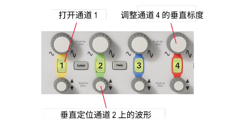
Vertical controls on an oscilloscope are usually located in the area labelled "Vertical". These controls allow you to adjust the display in the vertical direction. For example, there is a control that specifies the number of voltages per cell (scale) on the y-axis of the display grid. You can zoom in on the waveform by decreasing the number of voltages per cell, or you can zoom out by increasing the number. There is also a control for controlling the vertical offset of the waveform. This control pans the entire waveform up and down in the display. You can see the vertical control area of the Keysight InfiniiVision 2000 X-Series Oscilloscopes in Figure 16.
Horizontal Controls
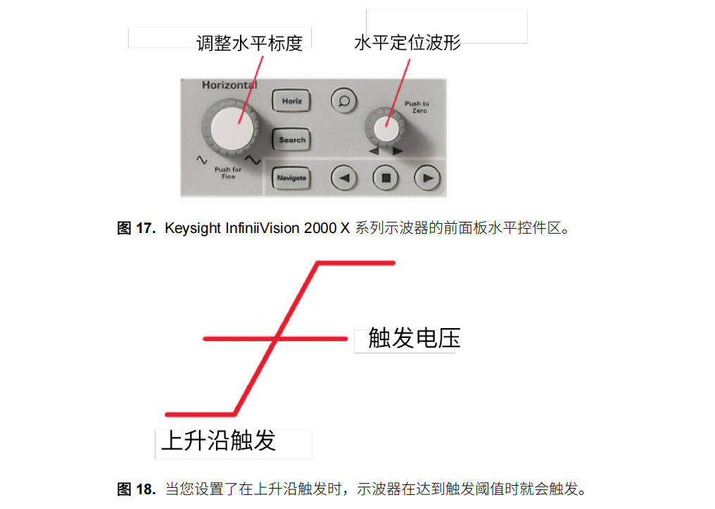
The horizontal controls on the oscilloscope are usually located on the front panel in the area labelled "Horizontal". These controls allow you to adjust the horizontal scale of the display. There is a control to specify the time per frame on the x-axis. Again, decreasing the time per frame allows you to zoom in on a narrower time range. This area also has a control for the horizontal delay (offset). This control allows you to scan a time period. You can see the horizontal control area of the Keysight InfiniiVision 2000 X-Series Oscilloscopes in Figure 17.
Pulse Width Trigger
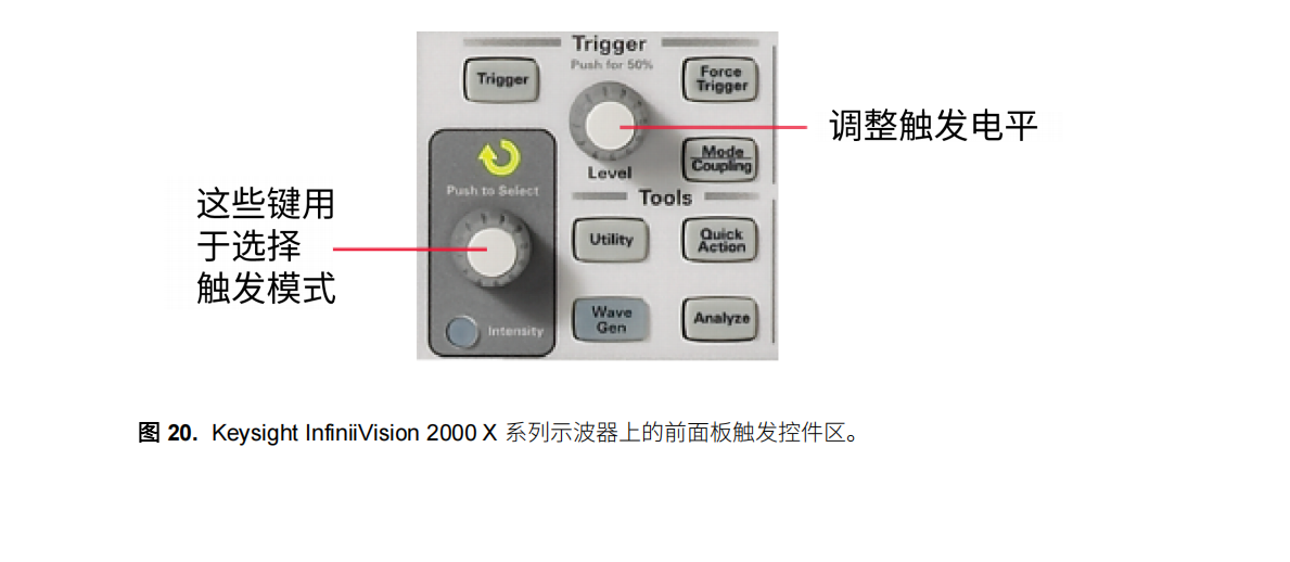
Pulse width triggering is similar to burr triggering when you need to find a specific pulse width. However, you can usually trigger a pulse of any specified width and you can select the polarity (negative or positive) of the pulse to trigger. You can also set the horizontal position of the trigger. This allows you to see what happens before and after the trigger. For example, you can perform a burr trigger, find the error, and then look at the signal before the trigger to determine the cause of the burr. If you set the Horizontal Delay to zero, the trigger event will be placed in the middle of the screen horizontally. Events that occur before the trigger will be on the left side of the screen, and events that occur after the trigger will be on the right side of the screen. You can also set the Trigger Coupling and set the input source you want to trigger. You do not have to trigger your own signals, but you can trigger related signals as well. Figure 20 shows the trigger control area on the front panel of the oscilloscope.
Input Controls
There are usually two or four analogue channels on an oscilloscope. These channels are numbered, and there is usually a button associated with each particular channel that turns the channel on or off. There may also be an option to specify AC or DC coupling. If DC coupling is selected, the entire signal will be input. Conversely, AC coupling will block the DC component and centre the waveform around 0 volts (ground). In addition, the probe impedance can be specified for each channel using the selector buttons. Sampling type can also be selected using the input controls. There are two basic signal sampling methods:
- Real-time sampling Real-time sampling usually takes enough samples of the waveform so that a complete picture of the waveform is captured at each acquisition. With real-time sampling, some of today's higher-performance oscilloscopes can capture signals with bandwidths up to 32 GHz in a single acquisition. Equivalent Time Sampling Equivalent Time Sampling
- Equivalent Time Sampling Equivalent Time Sampling builds up a waveform over multiple acquisitions. A portion of the signal is sampled in the first acquisition, then another portion is sampled in the second acquisition, and so on. All of this information is then combined to reconstruct the waveform. Equivalent Time Sampling is useful for high-frequency signals (> 32 GHz) that are too fast to sample in real time.
Software Keys
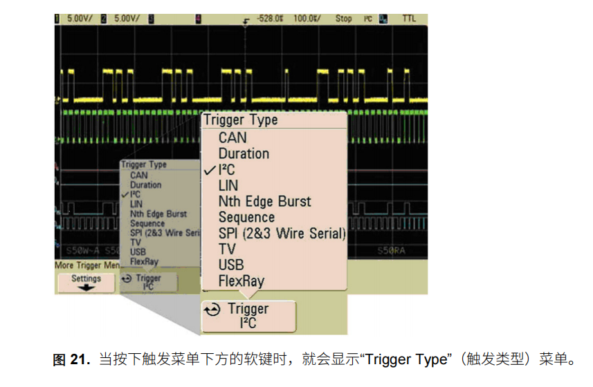
Soft keys are often found on oscilloscopes that do not have the Windows operating system installed (see Figure 8 for a picture of the soft keys). Use these softkeys to navigate the menu system on the oscilloscope display. Figure 21 shows what the pull-down menus look like when the softkeys are pressed. The figure shows the menu for selecting the trigger mode. You can scroll through the selections by pressing the softkeys consecutively, and there is a knob on the front panel that is also used to scroll through the selections. When the softkey below the Trigger menu is pressed, the Trigger Type menu is displayed.
Basic Measurements
A wide range of measurements can be performed on waveforms using a digital oscilloscope. The range and complexity of measurements depends on the feature set of the oscilloscope. Figure 22 shows a blank display of a Keysight 8000 series oscilloscope. Note the measurement buttons/icons listed on the far left side of the screen. These icons can be dragged onto the waveform with the mouse and the measurement results will be calculated. These icons are also convenient because the icons themselves tell you what measurement you are making.
Basic Front Panel Controls
Typically, oscilloscopes are operated using the knobs and buttons on the front panel. In addition to the controls on the front panel, many high-end oscilloscopes are now equipped with an operating system, so they can be operated in the same way as a computer. You can connect a mouse and keyboard to the oscilloscope and use the mouse to adjust the controls by using the pull-down menus and buttons on the display. In addition, some oscilloscopes are equipped with touchscreens that allow you to access menus using a stylus or your fingertips.
Before You Begin ......
When you first sit down with the oscilloscope, check that the input channel you are using is turned on. Press the [Default Settings] button (if available). This will return the oscilloscope to its original default state. Then press the Autoscale button (if available). This function will automatically set the vertical and horizontal scales if your waveform does not appear well on the display. Use this as a starting point to make any necessary adjustments. If you lose track of the waveform or have difficulty displaying it, repeat these steps. Most oscilloscopes contain at least four main areas on the front panel: vertical controls, horizontal controls, trigger controls, and input controls.
Vertical Controls
Vertical controls on an oscilloscope are usually located in the area labelled "Vertical". These controls allow you to adjust the display in the vertical direction. For example, there is a control that specifies the number of voltages per cell (scale) on the y-axis of the display grid. You can zoom in on the waveform by decreasing the number of voltages per cell, or you can zoom out by increasing the number. There is also a control for controlling the vertical offset of the waveform. This control pans the entire waveform up and down in the display. You can see the vertical control area of the Keysight InfiniiVision 2000 X-Series Oscilloscopes in Figure 16.
Horizontal Controls
The horizontal controls on the oscilloscope are usually located on the front panel in the area labelled "Horizontal". These controls allow you to adjust the horizontal scale of the display. There is a control to specify the time per frame on the x-axis. Again, decreasing the time per frame allows you to zoom in on a narrower time range. This area also has a control for the horizontal delay (offset). This control allows you to scan a time period. You can see the horizontal control area of the Keysight InfiniiVision 2000 X-Series Oscilloscopes in Figure 17.
Pulse Width Trigger
Pulse width triggering is similar to burr triggering when you need to find a specific pulse width. However, you can usually trigger a pulse of any specified width and you can select the polarity (negative or positive) of the pulse to trigger. You can also set the horizontal position of the trigger. This allows you to see what happens before and after the trigger. For example, you can perform a burr trigger, find the error, and then look at the signal before the trigger to determine the cause of the burr. If you set the Horizontal Delay to zero, the trigger event will be placed in the middle of the screen horizontally. Events that occur before the trigger will be on the left side of the screen, and events that occur after the trigger will be on the right side of the screen. You can also set the Trigger Coupling and set the input source you want to trigger. You do not have to trigger your own signals, but you can trigger related signals as well. Figure 20 shows the trigger control area on the front panel of the oscilloscope.
Input Controls
There are usually two or four analogue channels on an oscilloscope. These channels are numbered, and there is usually a button associated with each particular channel that turns the channel on or off. There may also be an option to specify AC or DC coupling. If DC coupling is selected, the entire signal will be input. Conversely, AC coupling will block the DC component and centre the waveform around 0 volts (ground). In addition, the probe impedance can be specified for each channel using the selector buttons. Sampling type can also be selected using the input controls. There are two basic signal sampling methods:
- Real-time sampling Real-time sampling usually takes enough samples of the waveform so that a complete picture of the waveform is captured at each acquisition. With real-time sampling, some of today's higher-performance oscilloscopes can capture signals with bandwidths up to 32 GHz in a single acquisition. Equivalent Time Sampling Equivalent Time Sampling
- Equivalent Time Sampling Equivalent Time Sampling builds up a waveform over multiple acquisitions. A portion of the signal is sampled in the first acquisition, then another portion is sampled in the second acquisition, and so on. All of this information is then combined to reconstruct the waveform. Equivalent Time Sampling is useful for high-frequency signals (> 32 GHz) that are too fast to sample in real time.
Software Keys
Soft keys are often found on oscilloscopes that do not have the Windows operating system installed (see Figure 8 for a picture of the soft keys). Use these softkeys to navigate the menu system on the oscilloscope display. Figure 21 shows what the pull-down menus look like when the softkeys are pressed. The figure shows the menu for selecting the trigger mode. You can scroll through the selections by pressing the softkeys consecutively, and there is a knob on the front panel that is also used to scroll through the selections. When the softkey below the Trigger menu is pressed, the Trigger Type menu is displayed.
Basic Measurements
A wide range of measurements can be performed on waveforms using a digital oscilloscope. The range and complexity of measurements depends on the feature set of the oscilloscope. Figure 22 shows a blank display of a Keysight 8000 series oscilloscope. Note the measurement buttons/icons listed on the far left side of the screen. These icons can be dragged onto the waveform with the mouse and the measurement results will be calculated. These icons are also convenient because the icons themselves tell you what measurement you are making.