


The main purpose of an oscilloscope is signal integrity


Signal Integrity
The main purpose of an oscilloscope is to provide an accurate visual display of the electrical signal. For this reason, signal integrity is very important. Signal integrity is the ability of an oscilloscope to reconstruct a waveform so that it accurately represents the original signal. If the signal integrity of an oscilloscope is low, it is useless. Because when the waveform on the oscilloscope does not have the same shape or characteristics as the real signal, it is meaningless to perform the test. However, it is important to remember that no matter how good the oscilloscope is, the waveform on the oscilloscope is never an accurate representation of the real signal. This is because when you connect an oscilloscope to a circuit, the oscilloscope has become part of the circuit. In other words, there is some load effect. Although instrument manufacturers strive to minimize load effects, they are always present to some degree.
The appearance of an oscilloscope
In general, a modern digital oscilloscope is very similar to the oscilloscope shown in Figure 8. However, there are many different types of oscilloscopes, and yours may look quite different. Nevertheless, there are some basic features that are common to most oscilloscopes. The front panel of most oscilloscopes can be divided into a few basic sections: channel inputs, display, horizontal controls, vertical controls, and trigger controls. If your oscilloscope does not have a Microsoft Windows-based operating system, there may be a set of soft keys to control the on-screen menus.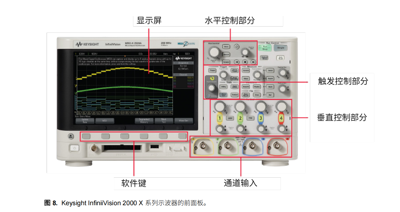
You can send signals to the oscilloscope through the channel inputs, which are the connectors used to plug in the probes. The display is the screen that shows these signals. The horizontal and vertical controls include knobs and buttons that control the horizontal axis (usually representing time) and vertical axis (representing voltage) of the signals displayed on the screen. The trigger control area allows you to tell the oscilloscope under what conditions you want the time base to begin acquisition. The rear panel of the oscilloscope is shown in Figure 9. As you can see, many oscilloscopes have the same connectivity features as on a personal computer. Examples include CD-ROM drives, CD-RW drives, DVD-RW drives, USB ports, serial ports, and external monitor, mouse, and keyboard inputs.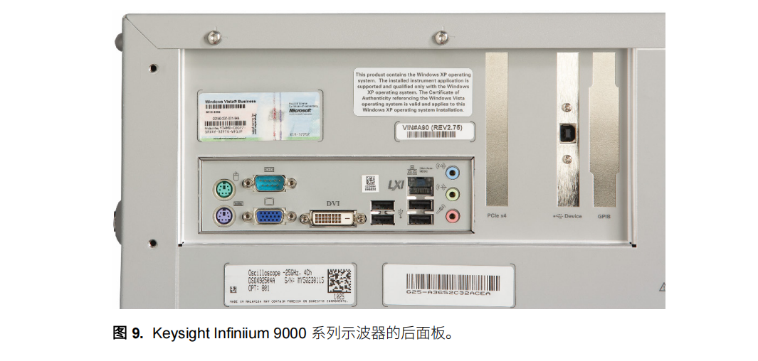