


Quickly understand the optical module eye chart test and use the equipment! Remember to bookmark and save!


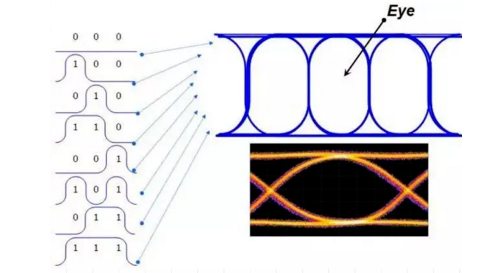
Optical module eye diagram test is a common optical test method used to measure the performance of optical modules during high-speed data transmission signal transmission, and is usually used to test parameters such as transparency, transmission distance and off-line storage of optical modules. The eye diagram of an optical module is an interlaced diagram of the photoelectric displacement waveform over a period of time collected using an oscilloscope and other equipment during high-speed data transmission, which can reflect the quality of the data transmission signal and the interference of the circuit. The name of the eye diagram comes from the appearance of the image resembles an "eye" shape, so called eye diagram.
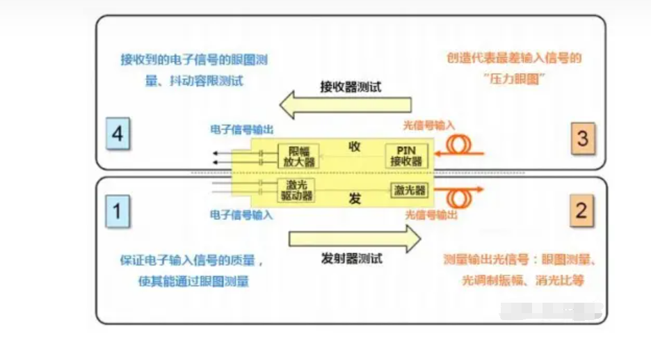
Optical module eye diagram testing is usually performed using a high-speed digital oscilloscope and waveform generator. The optical module transmits signals through optical fibers, and the interleaved signal waveforms are captured by the oscilloscope and then analyzed by eye diagram analysis software. Through the analysis of the eye diagram, the performance parameters of the optical module, such as noise, jitter, covariance, etc., can be calculated. These parameters can help users determine the performance and response time of the optical module as a basis for performance optimization and troubleshooting, ensuring the stability and reliability of the optical module in high-speed data transmission.
Optical module eye diagram testing is a complex optical testing technique that requires professional testing equipment and advanced testing skills. Therefore, before conducting eye diagram testing of optical modules, users are recommended to fully understand the test principles and methods, have adequate testing and analysis skills, and strictly follow the relevant safety guidelines and test protocols.
The following is a tutorial on eye diagram testing of optical modules (for reference only)
Confirm test requirements and equipment
First of all, the test requirements and the equipment used should be clearly defined, such as the clock rate of the test, the location of the test point at the measurement end, and the type of optical module. For high-speed serial data transmission, the use of 40G or 100G optical modules require certain equipment support.
Common equipment are high-speed oscilloscope, waveform generator, optical module, optical attenuator, optical fiber, clock source, synchronization receiver, etc.. Among them, the optical attenuator can be used to adjust the input optical signal strength.
Connect the test equipment and turn on the test
Connect the waveform generator, optical module and oscilloscope separately, and make sure the equipment is powered on and turned on. Generally speaking, the waveform generator is required to generate a fixed pattern data stream and modulate the data stream on a signal carrier with a constant frequency. If you want to test different modes of data stream, you need to switch between different modes. The optical signal strength at the input should be moderate, not too strong or too weak.
Adjust the oscilloscope sampling rate and attenuation control
According to the clock rate of the test system and the performance requirements of the optical module, decide the sampling rate of the oscilloscope. Set the oscilloscope parameters, such as clock rate, vertical and horizontal scaling, trigger settings, etc., through the control panel on the oscilloscope or software to obtain the best test results.
Start the test and observe the eye diagram
Turn on the oscilloscope and start the eye diagram test, acquire a segment of data and observe the eye diagram. The eye diagram should meet the following points:
The larger the opening width of the eye diagram, the better the quality of the signal transmitted by the optical module is represented.
The rise time and fall time of the eye diagram should be as short as possible.
The quality of the eye diagram can be improved by adjusting the test parameters, increasing the loss of the optical attenuator, or replacing other test equipment.
Ending the test
At the end of the test, return all equipment to normal and record the test results. Depending on the test requirements, further data analysis and data processing, such as bit error rate test (BER), may be required.
The above is a very simple tutorial for eye diagram testing of optical modules. For specific test requirements and equipment configurations, adjustments and optimizations need to be made according to the situation. In addition, care should be taken to prevent eye damage and safe work when conducting the test.
Optical module eye diagram test (test equipment, for reference only)
High-speed oscilloscopes:
Tektronix DPO/MSO70000DX series oscilloscopes
Keysight 86100D Infiniium DCA-X series eye diagram analyzer
Rohde&Schwarz R&S RTP eye diagram analyzer
Waveform Generators:
Tektronix AWG7 Series Waveform Generators
Keysight M8190A High Speed Arbitrary Waveform Generator
Optical modules:
QSFP28 optical modules, such as Finisar FTL4C1QE1C, Oclaro LR4, QLogic QLE89xx-CU-CK, etc.
Optical attenuators:
JDSU OLA-55 Variable Optical Attenuator
EXFO FVA Series Variable Optical Attenuators
Anritsu MP1632A fixed optical attenuator
Optical fiber:
OM3 or OM4 multimode fiber, such as Corning ClearCurve OM4, DRAKA 50/125 OM3, Sumitomo OM4, etc.
SMF single-mode fiber, such as Corning SMF-28 Ultra, Fujikura FIM-SMF-28, etc.
Clock sources:
HP 81110A 165 MHz pulse source
Agilent 33250A function generator
Synchronous receivers:
Agilent E5867A high-speed data receiver
Note: The above equipment list is for reference only. The specific reference model and selection should be based on test requirements, budget and suppliers.
Optical module test equipment manufacturers (for reference only)
Keysight Technologies
Keysight Technologies is a global leader in electronic test and measurement, providing a variety of equipment for testing optical module eye diagrams, including high-speed oscilloscopes, eye diagram analyzers, signal generators, BER testers, and more. Keysight's products are used in the production and testing of data centers, communications, aerospace, defense, and various electronic devices.

Anritsu Corporation
Anritsu is a Japanese manufacturer of electronic equipment for communication testing, metrology medical and industrial automation. anritsu's products include optical module eye diagram testers, BER testers, and high-speed digital signal generators, which are widely used in communication, semiconductor, and computer fields.

Tektronix, Inc.
Tektronix is an American manufacturer of electronic test instruments, offering a wide range of optical modules and high-speed digital communications test instruments, including high-speed oscilloscopes and BER analyzers for applications in fiber optic and wired networks, communications and computers, aerospace and defense.

Rohde & Schwarz
Rohde & Schwarz is a German electronics manufacturer specializing in high-end communication and test equipment. Its products cover a wide range of applications, such as mobile communications, satellite communications, broadcasting, radio and radio monitoring, security checks, etc. Rohde & Schwarz's eye diagram test instruments use unique digital signal processing technology to help users obtain accurate measurement results.
EXFO Inc.
EXFO is a Canadian manufacturer of electronic equipment focused on optical measurement and test technology.EXFO's products include optical module eye diagram testers, fiber optic testers, and optical attenuators for a wide range of applications in wired and wireless networks, manufacturers and operators, defense and security.

Optical module eye diagram test is a common optical test method used to measure the performance of optical modules during high-speed data transmission signal transmission, and is usually used to test parameters such as transparency, transmission distance and off-line storage of optical modules. The eye diagram of an optical module is an interlaced diagram of the photoelectric displacement waveform over a period of time collected using an oscilloscope and other equipment during high-speed data transmission, which can reflect the quality of the data transmission signal and the interference of the circuit. The name of the eye diagram comes from the appearance of the image resembles an "eye" shape, so called eye diagram.
Optical module eye diagram testing is usually performed using a high-speed digital oscilloscope and waveform generator. The optical module transmits signals through optical fibers, and the interleaved signal waveforms are captured by the oscilloscope and then analyzed by eye diagram analysis software. Through the analysis of the eye diagram, the performance parameters of the optical module, such as noise, jitter, covariance, etc., can be calculated. These parameters can help users determine the performance and response time of the optical module as a basis for performance optimization and troubleshooting, ensuring the stability and reliability of the optical module in high-speed data transmission.
Optical module eye diagram testing is a complex optical testing technique that requires professional testing equipment and advanced testing skills. Therefore, before conducting eye diagram testing of optical modules, users are recommended to fully understand the test principles and methods, have adequate testing and analysis skills, and strictly follow the relevant safety guidelines and test protocols.
The following is a tutorial on eye diagram testing of optical modules (for reference only)
Confirm test requirements and equipment
First of all, the test requirements and the equipment used should be clearly defined, such as the clock rate of the test, the location of the test point at the measurement end, and the type of optical module. For high-speed serial data transmission, the use of 40G or 100G optical modules require certain equipment support.
Common equipment are high-speed oscilloscope, waveform generator, optical module, optical attenuator, optical fiber, clock source, synchronization receiver, etc.. Among them, the optical attenuator can be used to adjust the input optical signal strength.
Connect the test equipment and turn on the test
Connect the waveform generator, optical module and oscilloscope separately, and make sure the equipment is powered on and turned on. Generally speaking, the waveform generator is required to generate a fixed pattern data stream and modulate the data stream on a signal carrier with a constant frequency. If you want to test different modes of data stream, you need to switch between different modes. The optical signal strength at the input should be moderate, not too strong or too weak.
Adjust the oscilloscope sampling rate and attenuation control
According to the clock rate of the test system and the performance requirements of the optical module, decide the sampling rate of the oscilloscope. Set the oscilloscope parameters, such as clock rate, vertical and horizontal scaling, trigger settings, etc., through the control panel on the oscilloscope or software to obtain the best test results.
Start the test and observe the eye diagram
Turn on the oscilloscope and start the eye diagram test, acquire a segment of data and observe the eye diagram. The eye diagram should meet the following points:
The larger the opening width of the eye diagram, the better the quality of the signal transmitted by the optical module is represented.
The rise time and fall time of the eye diagram should be as short as possible.
The quality of the eye diagram can be improved by adjusting the test parameters, increasing the loss of the optical attenuator, or replacing other test equipment.
Ending the test
At the end of the test, return all equipment to normal and record the test results. Depending on the test requirements, further data analysis and data processing, such as bit error rate test (BER), may be required.
The above is a very simple tutorial for eye diagram testing of optical modules. For specific test requirements and equipment configurations, adjustments and optimizations need to be made according to the situation. In addition, care should be taken to prevent eye damage and safe work when conducting the test.
Optical module eye diagram test (test equipment, for reference only)
High-speed oscilloscopes:
Tektronix DPO/MSO70000DX series oscilloscopes
Keysight 86100D Infiniium DCA-X series eye diagram analyzer
Rohde&Schwarz R&S RTP eye diagram analyzer
Waveform Generators:
Tektronix AWG7 Series Waveform Generators
Keysight M8190A High Speed Arbitrary Waveform Generator
Optical modules:
QSFP28 optical modules, such as Finisar FTL4C1QE1C, Oclaro LR4, QLogic QLE89xx-CU-CK, etc.
Optical attenuators:
JDSU OLA-55 Variable Optical Attenuator
EXFO FVA Series Variable Optical Attenuators
Anritsu MP1632A fixed optical attenuator
Optical fiber:
OM3 or OM4 multimode fiber, such as Corning ClearCurve OM4, DRAKA 50/125 OM3, Sumitomo OM4, etc.
SMF single-mode fiber, such as Corning SMF-28 Ultra, Fujikura FIM-SMF-28, etc.
Clock sources:
HP 81110A 165 MHz pulse source
Agilent 33250A function generator
Synchronous receivers:
Agilent E5867A high-speed data receiver
Note: The above equipment list is for reference only. The specific reference model and selection should be based on test requirements, budget and suppliers.
Optical module test equipment manufacturers (for reference only)
Keysight Technologies
Keysight Technologies is a global leader in electronic test and measurement, providing a variety of equipment for testing optical module eye diagrams, including high-speed oscilloscopes, eye diagram analyzers, signal generators, BER testers, and more. Keysight's products are used in the production and testing of data centers, communications, aerospace, defense, and various electronic devices.
Anritsu Corporation
Anritsu is a Japanese manufacturer of electronic equipment for communication testing, metrology medical and industrial automation. anritsu's products include optical module eye diagram testers, BER testers, and high-speed digital signal generators, which are widely used in communication, semiconductor, and computer fields.
Tektronix, Inc.
Tektronix is an American manufacturer of electronic test instruments, offering a wide range of optical modules and high-speed digital communications test instruments, including high-speed oscilloscopes and BER analyzers for applications in fiber optic and wired networks, communications and computers, aerospace and defense.
Rohde & Schwarz
Rohde & Schwarz is a German electronics manufacturer specializing in high-end communication and test equipment. Its products cover a wide range of applications, such as mobile communications, satellite communications, broadcasting, radio and radio monitoring, security checks, etc. Rohde & Schwarz's eye diagram test instruments use unique digital signal processing technology to help users obtain accurate measurement results.
EXFO Inc.
EXFO is a Canadian manufacturer of electronic equipment focused on optical measurement and test technology.EXFO's products include optical module eye diagram testers, fiber optic testers, and optical attenuators for a wide range of applications in wired and wireless networks, manufacturers and operators, defense and security.