


What is needed for optical communication module automation test equipment? How to meet the demand?


Optical modules need to test indicators:
Bit Rate: the optical module modulates the rate of the optical signal
Eye Ampl: Eye signal amplitude
Jitter
Extinction Ratio
Take 25G high-speed optical module test as an example, to introduce the current domestic optical module manufacturers to use the test method. (The cost of environment construction varies depending on the test method.) Most of the optical module manufacturers are based on virtual instrument technology to design the automated test system for optical modules.
The optical module self-testing system integrates advanced domestic and foreign test instruments and equipment (optical oscilloscope, BER, optical power meter, optical attenuation meter, etc.), which are connected to PC through GPIB bus or other bus supported by VISA (VirtualInstrument Software), and the PC is controlled by the upper computer software system based on the virtual instrument to realize the Real-time control of each measurement instrument is realized on the PC side based on the upper computer software system control of the virtual instrument to complete the automated testing process of the module.
The test system solution generally separates the module's transmitter and receiver ends for debugging and measurement, and after initial testing and aging, unifies the final testing. As shown in Figure:
The performance index of the transmitting end of the optical module can basically be characterized by the information of the photoeye diagram at the transmitting end. As shown in the figure, the optical module under test combined with the test board converts the high-speed electrical signal provided by the BER into an optical signal, which is connected to the optical oscilloscope through a fiber optic jumper, while the Trigger end of the BER connects the synchronous clock signal to the oscilloscope to achieve signal synchronization and form an eye diagram on the optical oscilloscope.
The optical oscilloscope (86100d oscilloscope) needs to select the filter rate and center wavelength corresponding to the optical module to be tested, select the appropriate eye diagram template to match the formed eye diagram, and the test system sends the generated eye diagram information (emitted optical power, extinction ratio, eye diagram rise and fall time and eye diagram crossover point, etc.) to the host computer through the GBIP bus.
During the testing process, it is necessary to set the appropriate optical power and extinction ratio according to the target requirements of the module index, and at the same time to complete the calibration of the emitted optical power value of the module digital diagnosis with the actual value, adjust the bias current (Ibias) so that the optical power is within the qualified range, and the host computer will write the debugged data value into the EEPROM of the module through the test board.
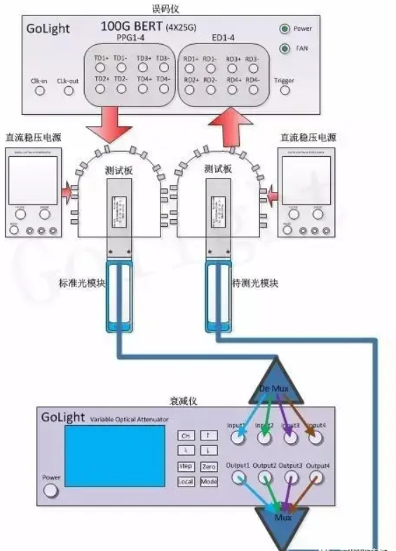
The receiver side of the optical module is mainly used for sensitivity testing. Generally, a standard optical module is selected as the standard optical transmitting source, based on the high-speed electrical signal generated by the BER to drive the optical module transmitting end through the test board to generate a standard signal source. The sensitivity test requires a programmable optical attenuator to attenuate the power of the signal, so that the receiver side of the optical module receives signals of different powers, and finally the sensitivity test is completed by comparing the BER of different optical powers through the BER. In the testing process, the alarm value is set first and the DMM value of the received optical power of the module is calibrated. By adjusting the programmable optical attenuator, the optical power value of the module at the receiving end of a specific BER (eg: BRT=10-12) is detected, which is the sensitivity index.
In the actual testing process, the BER under several optical power conditions is generally obtained by adjusting the optical attenuator, and then curve fitting and other methods are used to estimate the module sensitivity. By comparing the set alarm threshold, the signal loss indication (Los Assert), signal loss recovery indication (Los Dessert) and other indicators of the module are measured to meet the standard.
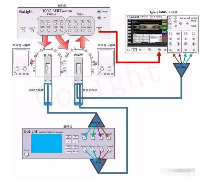
Optical module manufacturers generally perform the testing of module parameters again after aging the optical modules that have been tested separately at the transmitting and receiving ends to determine the changes in the functional parameters of the optical modules due to aging. The test of the module in the test scheme as shown above, can simultaneously complete the measurement of sensitivity and eye diagram optical indicators, in the actual test may need two BER to drive two test boards, respectively, to use only one BER of the two differential outputs to drive two test boards, respectively, you need to choose high-quality code generator (PPG).
Equipment list: keysight 86100D sampling oscilloscope, agilent 8164B optical wave measurement system, keysight 86105C oscilloscope 34 GHz optical/50 GHz electrical module
Optical modules need to test indicators:
Bit Rate: the optical module modulates the rate of the optical signal
Eye Ampl: Eye signal amplitude
Jitter
Extinction Ratio
Take 25G high-speed optical module test as an example, to introduce the current domestic optical module manufacturers to use the test method. (The cost of environment construction varies depending on the test method.) Most of the optical module manufacturers are based on virtual instrument technology to design the automated test system for optical modules.
The optical module self-testing system integrates advanced domestic and foreign test instruments and equipment (optical oscilloscope, BER, optical power meter, optical attenuation meter, etc.), which are connected to PC through GPIB bus or other bus supported by VISA (VirtualInstrument Software), and the PC is controlled by the upper computer software system based on the virtual instrument to realize the Real-time control of each measurement instrument is realized on the PC side based on the upper computer software system control of the virtual instrument to complete the automated testing process of the module.
The test system solution generally separates the module's transmitter and receiver ends for debugging and measurement, and after initial testing and aging, unifies the final testing. As shown in Figure:
The performance index of the transmitting end of the optical module can basically be characterized by the information of the photoeye diagram at the transmitting end. As shown in the figure, the optical module under test combined with the test board converts the high-speed electrical signal provided by the BER into an optical signal, which is connected to the optical oscilloscope through a fiber optic jumper, while the Trigger end of the BER connects the synchronous clock signal to the oscilloscope to achieve signal synchronization and form an eye diagram on the optical oscilloscope.
The optical oscilloscope (86100d oscilloscope) needs to select the filter rate and center wavelength corresponding to the optical module to be tested, select the appropriate eye diagram template to match the formed eye diagram, and the test system sends the generated eye diagram information (emitted optical power, extinction ratio, eye diagram rise and fall time and eye diagram crossover point, etc.) to the host computer through the GBIP bus.
During the testing process, it is necessary to set the appropriate optical power and extinction ratio according to the target requirements of the module index, and at the same time to complete the calibration of the emitted optical power value of the module digital diagnosis with the actual value, adjust the bias current (Ibias) so that the optical power is within the qualified range, and the host computer will write the debugged data value into the EEPROM of the module through the test board.
The receiver side of the optical module is mainly used for sensitivity testing. Generally, a standard optical module is selected as the standard optical transmitting source, based on the high-speed electrical signal generated by the BER to drive the optical module transmitting end through the test board to generate a standard signal source. The sensitivity test requires a programmable optical attenuator to attenuate the power of the signal, so that the receiver side of the optical module receives signals of different powers, and finally the sensitivity test is completed by comparing the BER of different optical powers through the BER. In the testing process, the alarm value is set first and the DMM value of the received optical power of the module is calibrated. By adjusting the programmable optical attenuator, the optical power value of the module at the receiving end of a specific BER (eg: BRT=10-12) is detected, which is the sensitivity index.
In the actual testing process, the BER under several optical power conditions is generally obtained by adjusting the optical attenuator, and then curve fitting and other methods are used to estimate the module sensitivity. By comparing the set alarm threshold, the signal loss indication (Los Assert), signal loss recovery indication (Los Dessert) and other indicators of the module are measured to meet the standard.
Optical module manufacturers generally perform the testing of module parameters again after aging the optical modules that have been tested separately at the transmitting and receiving ends to determine the changes in the functional parameters of the optical modules due to aging. The test of the module in the test scheme as shown above, can simultaneously complete the measurement of sensitivity and eye diagram optical indicators, in the actual test may need two BER to drive two test boards, respectively, to use only one BER of the two differential outputs to drive two test boards, respectively, you need to choose high-quality code generator (PPG).
Equipment list: keysight 86100D sampling oscilloscope, agilent 8164B optical wave measurement system, keysight 86105C oscilloscope 34 GHz optical/50 GHz electrical module