


Detection of optical modules emitting optical power, there are several common methods, save the collection!


The optical module generally undergoes a rigorous hardware test and electronic optical test before delivery. The electronic optical test is a key test of the compatibility mode of the optical module, and the hardware test is mainly a test of the main parameters, including the transmit laser power, receiver sensitivity, operating temperature, and reference point power flow.
A, the need for the optical module to send laser power
Send laser power (OutputPower) refers to the mean output laser power of the light module to push the end of the light source, also known as the output laser power. Enterprise: W or mW or dBm, unit conversion formula calculation: P (dBm) = 10Log (P / 1mW).
Optical module transmit laser power is the main parameter that endangers the optical module transmission spacing, when the transmit laser power is too small, the control module coordinator's received optical power will then be lower than the receiver sensitivity of the control module, the control module can not properly accept the data signal light; when the transmit laser power is too large, although in the coordinator can be used to enhance the optical attenuator to do the control module coordinator's received optical power category, but The required reference point power flow will also be slightly larger, will interfere with the data signal transmission quality and the use of the control module term.
Different light wavelength, transmission speed and transmission spacing of the optical module to send laser power are not the same, you can use the following four methods to query the optical module to send laser power, distinguish whether in all normal circumstances.
Second, the way to check the optical module to send laser power
1, the network switch loaded DDM information content
Data diagnostic role (DDM) as a "physician" to confirm the "disease" of the optical module, it can confirm the operational status of the optical module, but also real-time monitoring of the system optical module internal main parameters are not all normal. According to the alarm information of transmitting and receiving optical power, operating voltage, and reference point power flow detected to carry out comprehensive analysis, it can predict and analyze common failures, pinpoint the problem areas, reduce the recovery time of common failures, and reduce losses.
Network switch query DDM information content of different instructions, according to your actual use of the model to carry out the actual operation.
2、Eye diagram detection
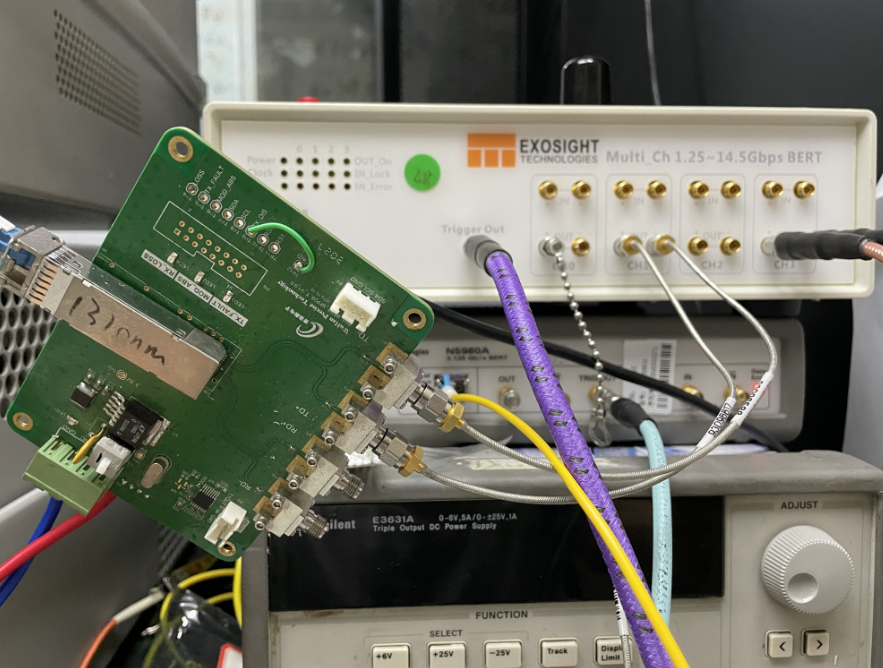
Optical module to send laser power can be indicated by the content of the optical eye diagram information at the transmitter, the following figure is the whole process of eye diagram detection of 25G optical module.
(1) According to the detection board will be given by the electronic signal of the BER into the optical signal light is not bright to pass to the 25G optical module, according to the optical fiber pigtail connected to the optical digital oscilloscope in;
(2) the Trigger end of the BER will synchronize the clock data signal connected to the digital oscilloscope, complete the data signal with the 歩, in the optical digital oscilloscope to generate the eye diagram;
(3) The optical digital oscilloscope needs to select the filter speed and core light wavelength corresponding to the 25G optical module, select the suitable eye diagram template to carry out the pairing of the generated eye diagram, and the content of the transformed eye diagram information will be sent to the computer (sending laser power, extinction ratio, eye diagram rising amplitude and eye diagram intersection point, etc.).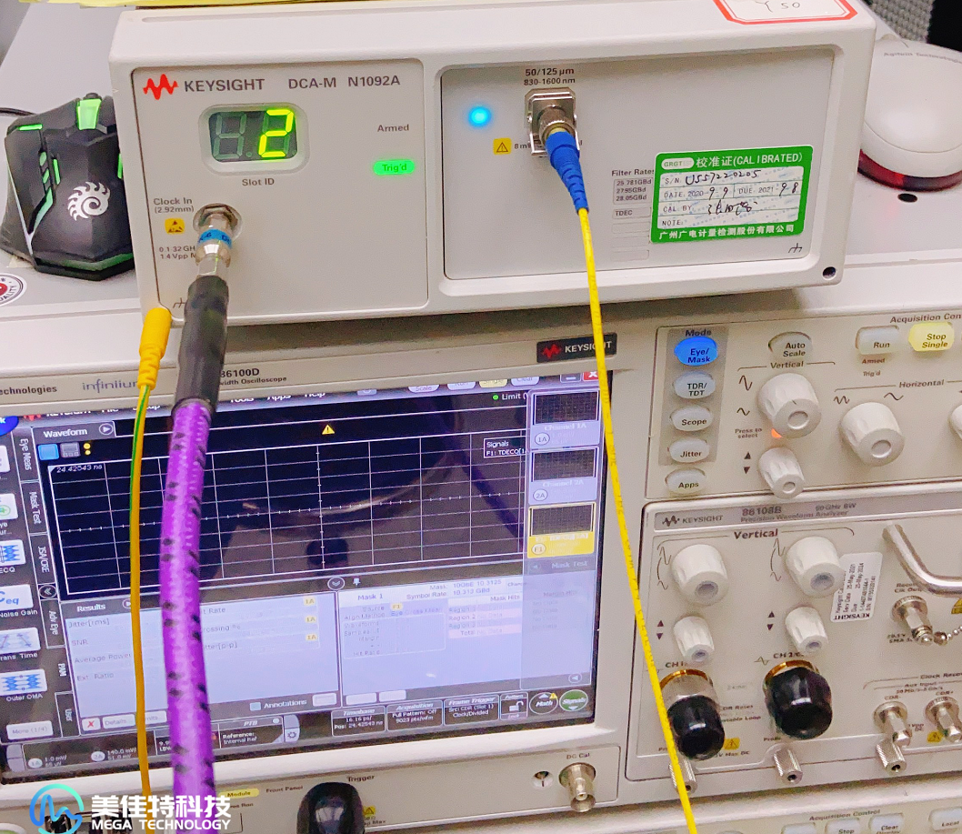
In order to make the detected 25G optical module transmit laser power in all normal transmit laser power range, the reference point electric flow can be adjusted to promote the laser power in the appropriate range.
3、Spectrum analyzer detection
(1) select FC-LC/SC connector type according to the type of optical module;
(2) Connect the FC connector end of FC-LC simplex leakage line to the "OpticalInput" socket of the spectrum analyzer;
(3) Connect the LC connector end of the FC-LC simplex drain line to the TX socket of the optical module;
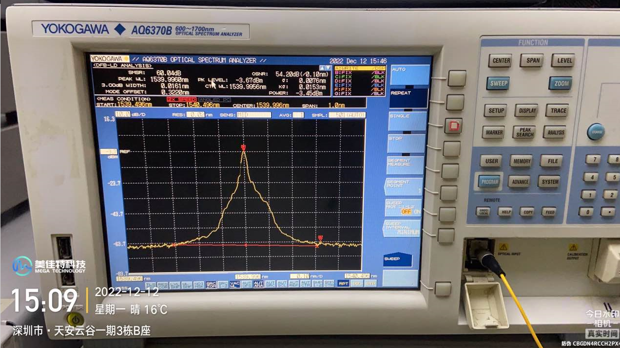
(4) Press and hold the "Auto" key on the spectrum meter; fully automatic loading of key parameters (including transmitting laser power), waiting for the spectrum meter's picture to show the area thoroughly, and then carry out the control module core optical wavelength value and side mode suppression ratio (SMSR) loading. The following figure is the spectrum analyzer test chart of 40GER4 optical module, the transmit laser power of the optical module on the chart is 2.8dBm;
(5) After the information content loading is carried out, pull out the leakage line, place the control module bottle cap at the parallel surface with the control module port number, and gently pull out the control module by applying the control module bottle cap.
4、Laser power detection
(1) determine the optical module with the use of optical fiber line type, interface mode, core optical wavelength;
(2) determine the optical power meter interface mode;
(3) according to the optical module, optical power meter interface mode and its optical module with the application of fiber optic line type to select the matching leak line;
(4) the network switch machine equipment power supply system, and to ensure that the network switch socket all normal and in the adminup situation; (5) the optical power meter will be started;
(5) will start the optical power meter, and will test the optical wavelength adjustment to the same wavelength as the core optical module;;
(6) the optical control module to be tested into the network switch socket, with a leaky line to connect the optical module to send the port number and optical power meter power adapter socket;
(7) load the data information on the optical power meter display, that is, the laser power detection results; can be converted according to the dbm function key to indicate the enterprise.
If you test the sending laser power has abnormal conditions, you can check the actual cause, the following explanation of several types of causes of sending laser power abnormal causes and solutions can you refer to.
Third, the cause of the optical module to send laser power abnormal causes
1, the common failure of the optical module itself, the luminous output power is not good, you can try to remove and replace the optical module;
2, optical module optical core hole stains or detection of fiber optic line hole stains caused by, can try to clean up the optical module hole and fiber optic line hole;;
3, the node has shortcomings, such as flange head, fusion fiber or machine equipment socket problems, you can try to gradually check.
Optical module hardware configuration of the main parameters of the test is very critical, not only to test the optical module to send laser power, but also to test other key parameters are not all normal, reliable dealers can give the optical module of the relevant inspection report, you are in the purchase of optical modules if there are doubts about its quality, you can need to check the relevant test results.
The optical module generally undergoes a rigorous hardware test and electronic optical test before delivery. The electronic optical test is a key test of the compatibility mode of the optical module, and the hardware test is mainly a test of the main parameters, including the transmit laser power, receiver sensitivity, operating temperature, and reference point power flow.
A, the need for the optical module to send laser power
Send laser power (OutputPower) refers to the mean output laser power of the light module to push the end of the light source, also known as the output laser power. Enterprise: W or mW or dBm, unit conversion formula calculation: P (dBm) = 10Log (P / 1mW).
Optical module transmit laser power is the main parameter that endangers the optical module transmission spacing, when the transmit laser power is too small, the control module coordinator's received optical power will then be lower than the receiver sensitivity of the control module, the control module can not properly accept the data signal light; when the transmit laser power is too large, although in the coordinator can be used to enhance the optical attenuator to do the control module coordinator's received optical power category, but The required reference point power flow will also be slightly larger, will interfere with the data signal transmission quality and the use of the control module term.
Different light wavelength, transmission speed and transmission spacing of the optical module to send laser power are not the same, you can use the following four methods to query the optical module to send laser power, distinguish whether in all normal circumstances.
Second, the way to check the optical module to send laser power
1, the network switch loaded DDM information content
Data diagnostic role (DDM) as a "physician" to confirm the "disease" of the optical module, it can confirm the operational status of the optical module, but also real-time monitoring of the system optical module internal main parameters are not all normal. According to the alarm information of transmitting and receiving optical power, operating voltage, and reference point power flow detected to carry out comprehensive analysis, it can predict and analyze common failures, pinpoint the problem areas, reduce the recovery time of common failures, and reduce losses.
Network switch query DDM information content of different instructions, according to your actual use of the model to carry out the actual operation.
2、Eye diagram detection
Optical module to send laser power can be indicated by the content of the optical eye diagram information at the transmitter, the following figure is the whole process of eye diagram detection of 25G optical module.
(1) According to the detection board will be given by the electronic signal of the BER into the optical signal light is not bright to pass to the 25G optical module, according to the optical fiber pigtail connected to the optical digital oscilloscope in;
(2) the Trigger end of the BER will synchronize the clock data signal connected to the digital oscilloscope, complete the data signal with the 歩, in the optical digital oscilloscope to generate the eye diagram;
(3) The optical digital oscilloscope needs to select the filter speed and core light wavelength corresponding to the 25G optical module, select the suitable eye diagram template to carry out the pairing of the generated eye diagram, and the content of the transformed eye diagram information will be sent to the computer (sending laser power, extinction ratio, eye diagram rising amplitude and eye diagram intersection point, etc.).
In order to make the detected 25G optical module transmit laser power in all normal transmit laser power range, the reference point electric flow can be adjusted to promote the laser power in the appropriate range.
3、Spectrum analyzer detection
(1) select FC-LC/SC connector type according to the type of optical module;
(2) Connect the FC connector end of FC-LC simplex leakage line to the "OpticalInput" socket of the spectrum analyzer;
(3) Connect the LC connector end of the FC-LC simplex drain line to the TX socket of the optical module;
(4) Press and hold the "Auto" key on the spectrum meter; fully automatic loading of key parameters (including transmitting laser power), waiting for the spectrum meter's picture to show the area thoroughly, and then carry out the control module core optical wavelength value and side mode suppression ratio (SMSR) loading. The following figure is the spectrum analyzer test chart of 40GER4 optical module, the transmit laser power of the optical module on the chart is 2.8dBm;
(5) After the information content loading is carried out, pull out the leakage line, place the control module bottle cap at the parallel surface with the control module port number, and gently pull out the control module by applying the control module bottle cap.
4、Laser power detection
(1) determine the optical module with the use of optical fiber line type, interface mode, core optical wavelength;
(2) determine the optical power meter interface mode;
(3) according to the optical module, optical power meter interface mode and its optical module with the application of fiber optic line type to select the matching leak line;
(4) the network switch machine equipment power supply system, and to ensure that the network switch socket all normal and in the adminup situation; (5) the optical power meter will be started;
(5) will start the optical power meter, and will test the optical wavelength adjustment to the same wavelength as the core optical module;;
(6) the optical control module to be tested into the network switch socket, with a leaky line to connect the optical module to send the port number and optical power meter power adapter socket;
(7) load the data information on the optical power meter display, that is, the laser power detection results; can be converted according to the dbm function key to indicate the enterprise.
If you test the sending laser power has abnormal conditions, you can check the actual cause, the following explanation of several types of causes of sending laser power abnormal causes and solutions can you refer to.
Third, the cause of the optical module to send laser power abnormal causes
1, the common failure of the optical module itself, the luminous output power is not good, you can try to remove and replace the optical module;
2, optical module optical core hole stains or detection of fiber optic line hole stains caused by, can try to clean up the optical module hole and fiber optic line hole;;
3, the node has shortcomings, such as flange head, fusion fiber or machine equipment socket problems, you can try to gradually check.
Optical module hardware configuration of the main parameters of the test is very critical, not only to test the optical module to send laser power, but also to test other key parameters are not all normal, reliable dealers can give the optical module of the relevant inspection report, you are in the purchase of optical modules if there are doubts about its quality, you can need to check the relevant test results.