


Digital oscilloscope structure characteristics of the whole machine


Digital oscilloscopes generally have a storage memory function, which can store the instantaneous signal waveform at any time during the measurement, and can capture the moment of signal change for observation. As shown in the figure, the entire structure of a typical digital oscilloscope. As can be seen from the figure, the digital oscilloscope is divided into two parts, the left part is the display part of the signal waveform and data, the right part is the control part of the oscilloscope, including the key knob area, probe connection area.
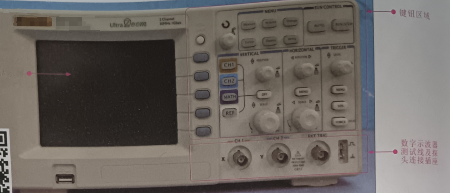
Display
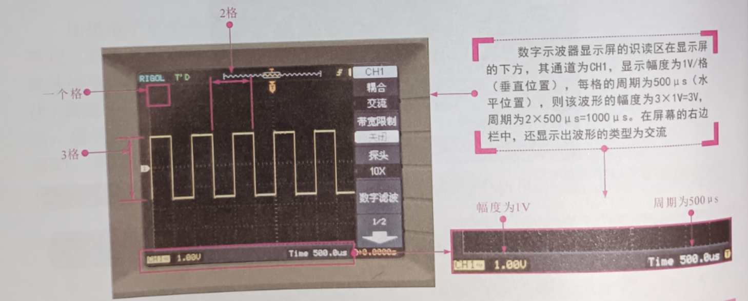
The display of the digital oscilloscope is the part that shows the measurement results and the current working status of the equipment, and the operation of parameter setting, measurement mode or setting adjustment before or during the measurement is also based on the display. As shown in the figure, the display of a typical digital oscilloscope, you can see that the display can directly display the type of waveform, the amplitude of each frame of the screen, the size of the cycle, etc., through the data displayed on the oscilloscope screen can be easily read out the amplitude and period of the waveform.
Key area
Key area is the main control part of the digital oscilloscope, each key has its own function, mastering the function of each key is a prerequisite for learning to use the digital oscilloscope. In the next section we will take the actual digital oscilloscope as an example to introduce the application of the function of each key button in detail.
Probe connection area
The probe connection area of the digital oscilloscope is the area where the oscilloscope test probes are connected. Probe connection area needs to be applied with the key creation area, the relevant mode settings should meet the corresponding relationship. For example, channel 1 (CHI signal input) corresponds to the CH1 button of the keyboard button area, channel 2 (CH2 signal input) corresponds to the CH2 button of the key area, as shown in the figure.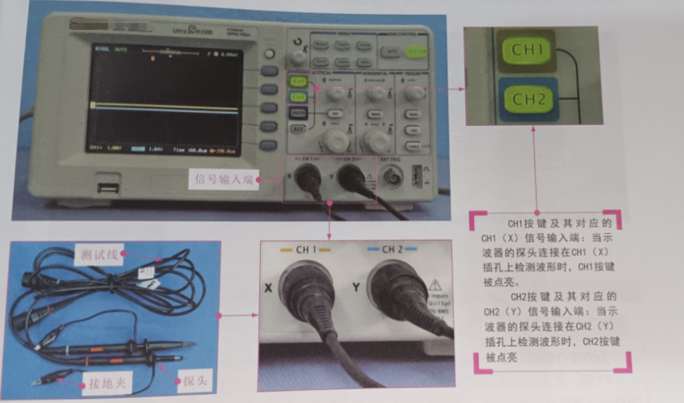
Digital oscilloscopes generally have a storage memory function, which can store the instantaneous signal waveform at any time during the measurement, and can capture the moment of signal change for observation. As shown in the figure, the entire structure of a typical digital oscilloscope. As can be seen from the figure, the digital oscilloscope is divided into two parts, the left part is the display part of the signal waveform and data, the right part is the control part of the oscilloscope, including the key knob area, probe connection area.
Display
The display of the digital oscilloscope is the part that shows the measurement results and the current working status of the equipment, and the operation of parameter setting, measurement mode or setting adjustment before or during the measurement is also based on the display. As shown in the figure, the display of a typical digital oscilloscope, you can see that the display can directly display the type of waveform, the amplitude of each frame of the screen, the size of the cycle, etc., through the data displayed on the oscilloscope screen can be easily read out the amplitude and period of the waveform.
Key area
Key area is the main control part of the digital oscilloscope, each key has its own function, mastering the function of each key is a prerequisite for learning to use the digital oscilloscope. In the next section we will take the actual digital oscilloscope as an example to introduce the application of the function of each key button in detail.
Probe connection area
The probe connection area of the digital oscilloscope is the area where the oscilloscope test probes are connected. Probe connection area needs to be applied with the key creation area, the relevant mode settings should meet the corresponding relationship. For example, channel 1 (CHI signal input) corresponds to the CH1 button of the keyboard button area, channel 2 (CH2 signal input) corresponds to the CH2 button of the key area, as shown in the figure.