


Oscilloscope knowledge | What is an oscilloscope? The difference between analog and digital oscilloscopes?


What is an oscilloscope?
An oscilloscope is an electronic test and measurement instrument that displays electrical signals graphically in the form of an X-Y graph. Here, the horizontal (X) represents time and the vertical (Y) axis represents the magnitude of the voltage. Thus, an oscilloscope essentially shows a graph of how the voltage of an electrical signal varies over time. Hence, the early oscilloscopes were called oscilloscopes.
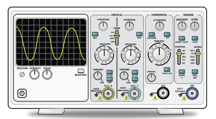
While multimeters also measure the voltage of electrical signals, oscilloscopes take such measurements to a new level by visually representing signals using waveforms. By plotting such waveforms, you can easily interpret the basic properties of a signal, such as amplitude, frequency, period, rise and fall times, and more.
For example, if you are designing a 12V power supply, a multimeter can only show if the output of the power supply is 12V. An oscilloscope, on the other hand, can display a waveform of the output power in which you can analyze noise, ripple, switching frequency, etc. and make any improvements or corrections.
Introduction to Oscilloscopes
Do you remember CRT televisions? Those bulky televisions had a cathode ray tube that was responsible for displaying the image on the screen. In fact, Ferdinand Braun experimented on the cathode ray tube when he developed the first oscilloscope in 1897. in 1899, Jonathan Zenneck developed the first oscilloscope by adding a beamforming plate and applying a linear horizontal deflection field.
Most of all these experiments produced useful laboratory equipment, but this changed in 1931 when Dr. V. K. Zworykin published a paper on CRTs that addressed the hot cathode and vacuum problems. This eventually led to the release of the first CRT-based portable oscilloscope by General Radio.
Interesting fact: Because the original oscilloscopes were developed using cathode ray tube technology, the early oscilloscopes were called cathode ray oscilloscopes or CROs for short. the term "CRO" became a popular industry term, and even today many senior engineers use CRO as a synonym for oscilloscope, even though most modern oscilloscopes are LCD monitors. The term "CRO" has become a popular industry term, and even today, many senior engineers use CRO as a synonym for oscilloscope, although most modern oscilloscopes are digital with LCD displays.
Semiconductor technology (processors, memory and data converters), the development of LCD display technology and the increasing cost of CRTs have led engineers to dabble in digital oscilloscopes. Most modern oscilloscopes are called digital storage oscilloscopes (DSO) because they capture and store traces for reinvestigation.
Types of Oscilloscopes
Basically, there are two types of oscilloscopes.
Analog
Digital
This classification has only become important since the development of digital storage oscilloscopes in the 1990s.
What is an analog oscilloscope?
The early CROs were analog oscilloscopes. They were very simple because they did not require any type of signal processing and the electrical signal was displayed as a waveform, just like using a high gain amplifier.
A simple CRO consists of a CRT (cathode ray tube), vertical and horizontal amplifiers, trigger unit, time base (scan generator) and power supply.
What is a digital oscilloscope?
The main difference between an analog oscilloscope and a digital oscilloscope is that in a digital oscilloscope, the analog signal is captured and converted to a digital signal using an analog-to-digital converter.
The advantage of using a digital oscilloscope is that digital data can be easily stored in digital memory. This is the main function of a digital storage oscilloscope or DSO, where a portion of the trace is captured and can be analyzed at a later time.
Before the use of LCD displays, digital oscilloscopes still used CRTs to display signals. This oscilloscope requires a digital-to-analog converter to convert the digital signal back to an analog signal and display it on the CRT. But for LCD monitors, we can avoid this step completely because the digital signal can be displayed directly on the LCD (after some conversion).
Digital oscilloscopes are further divided into.
Digital Storage Oscilloscopes (DSO)
Mixed Signal Oscilloscopes (MSO)
Digital fluorescent oscilloscopes (DPO)
Mixed Domain Oscilloscopes (MDO)
Digital Sampling Oscilloscopes (DCA-X)
How do oscilloscopes work?
Now that we have learned what an oscilloscope is and the two basic types of oscilloscopes, let's now try to understand how an oscilloscope works. Since there are generally analog and digital oscilloscopes, we will see how each of them works.
Analog Oscilloscopes
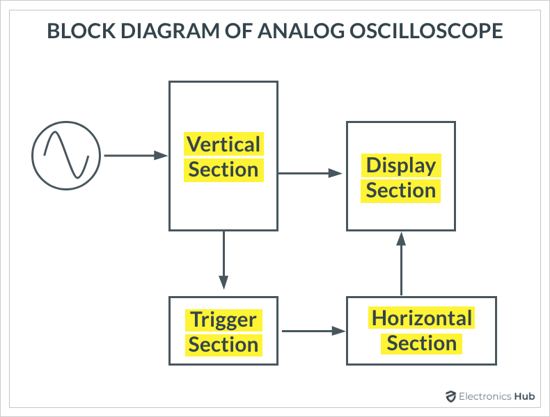
The CRT is the main part of all analog oscilloscopes. If we can understand how a CRT works, then we can easily know how to display waveforms on the screen of a CRT. The figure below shows the basic building blocks needed to display waveforms on a CRT.
The vertical section in the upper block diagram is responsible for sending the main image to the CRT's vertical deflection board. The vertical section amplifies or attenuates the input signal. The horizontal section is responsible for the movement of the electron beam from left to right. The trigger section determines when the waveform is drawn on the CRT.
Display System
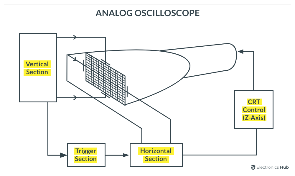
The figure below shows a simplified display system for an analog oscilloscope. The Z-axis circuit in the block diagram is responsible for controlling the brightness of the electron beam.
Vertical system
The basic form of an analog oscilloscope consists of an attenuator, preamplifier, delay line and main amplifier. The following figure shows the block diagram of the vertical system of the oscilloscope.
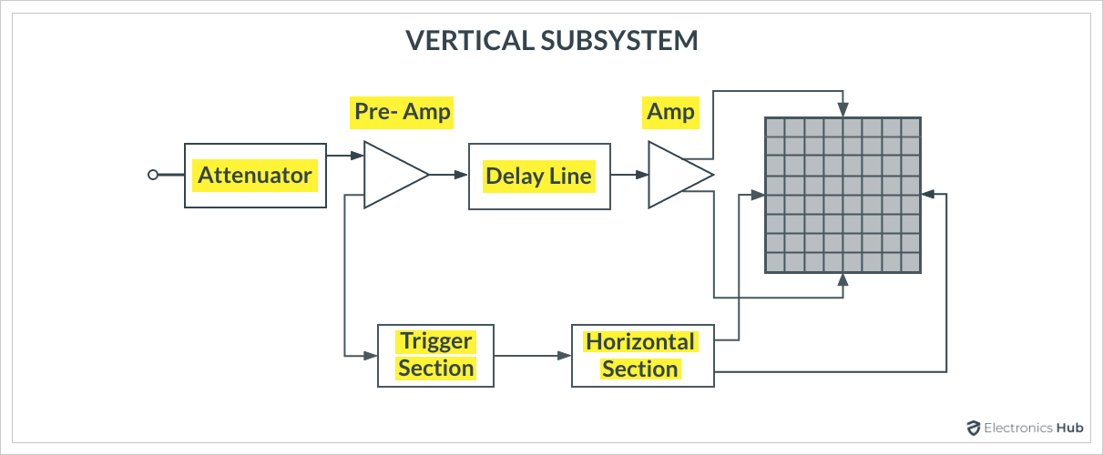
The attenuator section of the vertical system attenuates the input signal and also allows AC or DC coupling. The preamplifier stage is responsible for changing the DC component of the signal and therefore it allows to change the position of the alignment. The delay line of the vertical section allows to show the beginning of the signal.
Horizontal system
In order to display the signal correctly on the oscilloscope, the vertical and horizontal systems are equally important. While the vertical system is responsible for the amplitude part of the signal, the horizontal system brings 2 de - dimensionality, i.e. the time aspect of the signal.
The horizontal system provides deflection voltage to the horizontal plate to move the electron beam horizontally. To do this, the scan generator circuitry generates a sawtooth (or ramp) signal to control the scan rate of the beam.
The following figure shows a block diagram of an oscilloscope leveling system. The sawtooth or ramp signal rises linearly, allowing measurement of the time between two events. The scan generator is calibrated in time, hence the term time base.
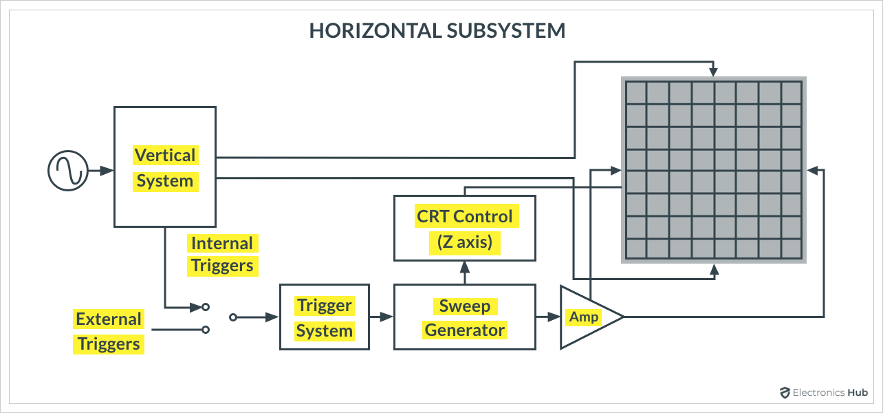
In addition to the time base, the Z-axis control system in front is also part of the horizontal system.
Trigger system
The last important part of the oscilloscope is the trigger system. This system determines the time at which the oscilloscope draws the waveform on the screen.
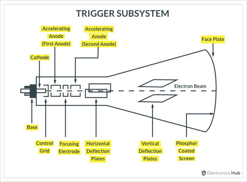
The CRT's screen is coated with phosphorus on the inside, so when electrons hit it, the screen glows. The horizontal system is responsible for moving the light beam from left to right. When it reaches the far right side of the screen, it quickly returns to the left to start the process again. This process is called scanning (or tracking or scanning).
The vertical system is responsible for moving the beam vertically. The trigger system of the oscilloscope ensures that the tracking of the waveform always starts from the same point on the screen.
Digital Oscilloscopes
Let's take a digital oscilloscope with a CRT as a reference to understand how it works. The figure below shows a simplified block diagram of a typical digital oscilloscope with a CRT display.
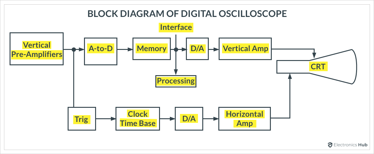
The main difference is the vertical system of the oscilloscope. So let's focus only on that, because the rest of the work will be similar to that of an analog oscilloscope.
After the attenuation and preamplifier stages, the analog signal is converted into a digital signal using an ADC (Analog to Digital Converter). The digital signal is then provided to the processing unit, which performs some signal processing (calculates basic parameters, stores them in memory, etc.). In order to display the signal on the CRT, the digital signal must be converted back to analog with the help of a digital-to-analog converter.
We present in this article an introductory guide to oscilloscopes. We learned what an oscilloscope is, what are the different types of oscilloscopes, the basic components of an oscilloscope and how analog and digital oscilloscopes work, there is still a lot to explore in the field of oscilloscopes.
What is an oscilloscope?
An oscilloscope is an electronic test and measurement instrument that displays electrical signals graphically in the form of an X-Y graph. Here, the horizontal (X) represents time and the vertical (Y) axis represents the magnitude of the voltage. Thus, an oscilloscope essentially shows a graph of how the voltage of an electrical signal varies over time. Hence, the early oscilloscopes were called oscilloscopes.
While multimeters also measure the voltage of electrical signals, oscilloscopes take such measurements to a new level by visually representing signals using waveforms. By plotting such waveforms, you can easily interpret the basic properties of a signal, such as amplitude, frequency, period, rise and fall times, and more.
For example, if you are designing a 12V power supply, a multimeter can only show if the output of the power supply is 12V. An oscilloscope, on the other hand, can display a waveform of the output power in which you can analyze noise, ripple, switching frequency, etc. and make any improvements or corrections.
Introduction to Oscilloscopes
Do you remember CRT televisions? Those bulky televisions had a cathode ray tube that was responsible for displaying the image on the screen. In fact, Ferdinand Braun experimented on the cathode ray tube when he developed the first oscilloscope in 1897. in 1899, Jonathan Zenneck developed the first oscilloscope by adding a beamforming plate and applying a linear horizontal deflection field.
Most of all these experiments produced useful laboratory equipment, but this changed in 1931 when Dr. V. K. Zworykin published a paper on CRTs that addressed the hot cathode and vacuum problems. This eventually led to the release of the first CRT-based portable oscilloscope by General Radio.
Interesting fact: Because the original oscilloscopes were developed using cathode ray tube technology, the early oscilloscopes were called cathode ray oscilloscopes or CROs for short. the term "CRO" became a popular industry term, and even today many senior engineers use CRO as a synonym for oscilloscope, even though most modern oscilloscopes are LCD monitors. The term "CRO" has become a popular industry term, and even today, many senior engineers use CRO as a synonym for oscilloscope, although most modern oscilloscopes are digital with LCD displays.
Semiconductor technology (processors, memory and data converters), the development of LCD display technology and the increasing cost of CRTs have led engineers to dabble in digital oscilloscopes. Most modern oscilloscopes are called digital storage oscilloscopes (DSO) because they capture and store traces for reinvestigation.
Types of Oscilloscopes
Basically, there are two types of oscilloscopes.
Analog
Digital
This classification has only become important since the development of digital storage oscilloscopes in the 1990s.
What is an analog oscilloscope?
The early CROs were analog oscilloscopes. They were very simple because they did not require any type of signal processing and the electrical signal was displayed as a waveform, just like using a high gain amplifier.
A simple CRO consists of a CRT (cathode ray tube), vertical and horizontal amplifiers, trigger unit, time base (scan generator) and power supply.
What is a digital oscilloscope?
The main difference between an analog oscilloscope and a digital oscilloscope is that in a digital oscilloscope, the analog signal is captured and converted to a digital signal using an analog-to-digital converter.
The advantage of using a digital oscilloscope is that digital data can be easily stored in digital memory. This is the main function of a digital storage oscilloscope or DSO, where a portion of the trace is captured and can be analyzed at a later time.
Before the use of LCD displays, digital oscilloscopes still used CRTs to display signals. This oscilloscope requires a digital-to-analog converter to convert the digital signal back to an analog signal and display it on the CRT. But for LCD monitors, we can avoid this step completely because the digital signal can be displayed directly on the LCD (after some conversion).
Digital oscilloscopes are further divided into.
Digital Storage Oscilloscopes (DSO)
Mixed Signal Oscilloscopes (MSO)
Digital fluorescent oscilloscopes (DPO)
Mixed Domain Oscilloscopes (MDO)
Digital Sampling Oscilloscopes (DCA-X)
How do oscilloscopes work?
Now that we have learned what an oscilloscope is and the two basic types of oscilloscopes, let's now try to understand how an oscilloscope works. Since there are generally analog and digital oscilloscopes, we will see how each of them works.
Analog Oscilloscopes
The CRT is the main part of all analog oscilloscopes. If we can understand how a CRT works, then we can easily know how to display waveforms on the screen of a CRT. The figure below shows the basic building blocks needed to display waveforms on a CRT.
The vertical section in the upper block diagram is responsible for sending the main image to the CRT's vertical deflection board. The vertical section amplifies or attenuates the input signal. The horizontal section is responsible for the movement of the electron beam from left to right. The trigger section determines when the waveform is drawn on the CRT.
Display System
The figure below shows a simplified display system for an analog oscilloscope. The Z-axis circuit in the block diagram is responsible for controlling the brightness of the electron beam.
Vertical system
The basic form of an analog oscilloscope consists of an attenuator, preamplifier, delay line and main amplifier. The following figure shows the block diagram of the vertical system of the oscilloscope.
The attenuator section of the vertical system attenuates the input signal and also allows AC or DC coupling. The preamplifier stage is responsible for changing the DC component of the signal and therefore it allows to change the position of the alignment. The delay line of the vertical section allows to show the beginning of the signal.
Horizontal system
In order to display the signal correctly on the oscilloscope, the vertical and horizontal systems are equally important. While the vertical system is responsible for the amplitude part of the signal, the horizontal system brings 2 de - dimensionality, i.e. the time aspect of the signal.
The horizontal system provides deflection voltage to the horizontal plate to move the electron beam horizontally. To do this, the scan generator circuitry generates a sawtooth (or ramp) signal to control the scan rate of the beam.
The following figure shows a block diagram of an oscilloscope leveling system. The sawtooth or ramp signal rises linearly, allowing measurement of the time between two events. The scan generator is calibrated in time, hence the term time base.
In addition to the time base, the Z-axis control system in front is also part of the horizontal system.
Trigger system
The last important part of the oscilloscope is the trigger system. This system determines the time at which the oscilloscope draws the waveform on the screen.
The CRT's screen is coated with phosphorus on the inside, so when electrons hit it, the screen glows. The horizontal system is responsible for moving the light beam from left to right. When it reaches the far right side of the screen, it quickly returns to the left to start the process again. This process is called scanning (or tracking or scanning).
The vertical system is responsible for moving the beam vertically. The trigger system of the oscilloscope ensures that the tracking of the waveform always starts from the same point on the screen.
Digital Oscilloscopes
Let's take a digital oscilloscope with a CRT as a reference to understand how it works. The figure below shows a simplified block diagram of a typical digital oscilloscope with a CRT display.
The main difference is the vertical system of the oscilloscope. So let's focus only on that, because the rest of the work will be similar to that of an analog oscilloscope.
After the attenuation and preamplifier stages, the analog signal is converted into a digital signal using an ADC (Analog to Digital Converter). The digital signal is then provided to the processing unit, which performs some signal processing (calculates basic parameters, stores them in memory, etc.). In order to display the signal on the CRT, the digital signal must be converted back to analog with the help of a digital-to-analog converter.
We present in this article an introductory guide to oscilloscopes. We learned what an oscilloscope is, what are the different types of oscilloscopes, the basic components of an oscilloscope and how analog and digital oscilloscopes work, there is still a lot to explore in the field of oscilloscopes.